Catalog excerpts

Disclaimer The information in this document is subject to change without notice and should not be construed as a commitment by ABB Oy. ABB Oy assumesno responsibility for any errors that may appear in this document. Copyright 2009 ABB Oy.All rights reserved. Trademarks ABB and Relion are registered trademarks of ABB Group. All other brand or product names mentioned in this document may be trademarks orregistered trademarks of their respective holders. >
Open the catalog to page 2
Table 2. Supported functions Functionality A B C D Protection > 1) Stabilized and instantaneous differential protection for two-winding transformers Ⴠ Ⴠ Ⴠ Ⴠ Numerical stabilized low impedance restricted earth-fault protection Ⴠ Ⴠ - - High impedance based restricted earth-fault protection - - Ⴠ Ⴠ Master Trip, instance 1 Ⴠ Ⴠ Ⴠ Ⴠ Master Trip, instance 2 Ⴠ Ⴠ Ⴠ Ⴠ HV-side protection Three-phase non-directional overcurrent protection, low stage, instance 1 Ⴠ Ⴠ Ⴠ Ⴠ Three-phase non-directional overcurrent protection, high stage, instance 1 Ⴠ Ⴠ Ⴠ Ⴠ Three-phase non-directional overcurrent protection,...
Open the catalog to page 4
Table 2. Supported functions, continued Functionality A B C D Arc protection, instance 3 o o o o Control Circuit-breaker control with interlocking Ⴠ Ⴠ Ⴠ Ⴠ Disconnector position indication, instance 1 Ⴠ Ⴠ Ⴠ Ⴠ Disconnector position indication, instance 2 Ⴠ Ⴠ Ⴠ Ⴠ Disconnector position indication, instance 3 Ⴠ Ⴠ Ⴠ Ⴠ Earthing switch indication Ⴠ Ⴠ Ⴠ Ⴠ Tap changer position indication Ⴠ Ⴠ Ⴠ Ⴠ Condition monitoring Circuit-breaker condition monitoring Ⴠ Ⴠ Ⴠ Ⴠ Trip circuit supervision, instance 1 Ⴠ Ⴠ Ⴠ Ⴠ Trip circuit supervision, instance 2 Ⴠ Ⴠ Ⴠ Ⴠ Measurement Disturbance recorder Ⴠ Ⴠ Ⴠ Ⴠ Three-phase...
Open the catalog to page 5
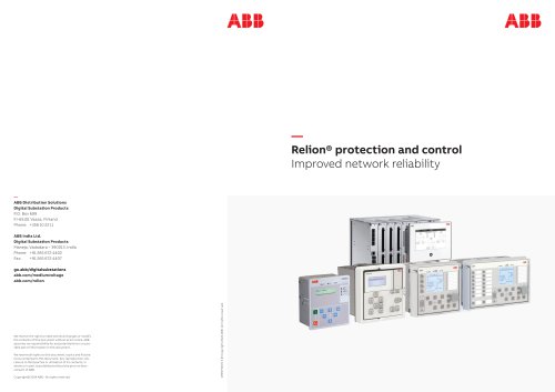
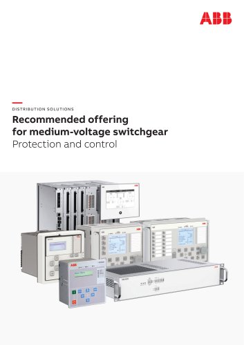
RET615 provides main protection for two-winding power transformers and power generator-transformer blocks. As of now, there are four standard configurations offering comprehensive protection functions for detection and elimination of operational disturbance conditions and power transformer faults.The standard configurations A and C areintended for power transformers with earthed HV side neutrals. The A configuration features low impedance REF protection whilethe C configuration offers high impedance REF protection. The B and D configurations fit transformers with a solidly earthed LV side...
Open the catalog to page 9
Table 3. Supported ABB solutions ABBs 615 series protection and control IEDstogether with the COM600 Station Automation device constitute a genuine IEC 61850 solution for reliable power distribution in utility and industrial power systems. To facilitate and streamline the system engineering ABBҒs IEDs are supplied with Connectivity Packages containing a compilation of software and IED-specific information including single-line diagram templates, a full IED data model including event and parameter lists. By utilizing the Connectivity Packages the IEDs can be readily configured via the PCM600...
Open the catalog to page 11
The IED offers control of one circuit breaker(by default HV side circuit breaker) with dedicated push-buttons for opening and closing. Interlocking schemes required by the application are configured with the signal matrix in PCM600. The IED continuously measures the high voltage (HV) side and the low-voltage (LV) side phase currents and the neutral current of the protected transformer. In addition, the IED calculates the maximum current demand value over a user-selectable pre-set time frame and the symmetrical components of the currents. Calculated values are also obtained from the...
Open the catalog to page 13
The condition monitoring functions of theIED constantly monitors the performance and the condition of the circuit breaker. The monitoring comprises the spring charging time, SF6 gas pressure, the travel-time and the inactivity time of the circuit breaker.The monitoring functions provide operationalCB history data, which can be used for scheduling preventive CB maintenance. To protect the IED from unauthorized access and to maintain information integrity, the IED is provided with a four-level, role-based authentication system with administrator- programmable individual passwords for the...
Open the catalog to page 14
The IED supports a range of communicationprotocols including IEC 61850, IEC60870-5-103, Modbus > and DNP3.Operational information and controls are available through these protocols.The IEC 61850 communicationimplementation supports all monitoring and control functions. Additionally, parameter setting and disturbance file records can be accessed using the IEC 61850 protocol. Disturbance files are available to any Ethernet- based application in the standard COMTRADE format. Further, the IED can send and receive binary signals from other IEDs (so called horizontal communication) using the...
Open the catalog to page 15
Table 5. Supported station communication interfaces and protocols Interfaces/Protocols Ethernet Serial 100BASE-TXRJ-45 100BASE-FX LC RS-232/RS-485 Fibre-optic ST IEC 61850 Ⴠ Ⴠ - - MODBUS RTU/ ASCII - - Ⴠ Ⴠ MODBUS TCP/ IP Ⴠ Ⴠ - - DNP3 (serial) - - Ⴠ Ⴠ DNP3 TCP/IP Ⴠ Ⴠ - - IEC 60870-5-103 - - Ⴠ ჀჀ = Supported >
Open the catalog to page 16
Table 6. Dimensions Description Value Width frame 179.8 mm case 164 mm Height frame 177 mm (4U) case 160 mm Depth 194 mm (153 + 41 mm) Weight IED 3.5 kg spare unit 1.8 kg Table 7. Power supply Description Type 1 Type 2 U > aux nominal 100, 110, 120, 220, 240 V AC,50 and 60 Hz 24, 30, 48, 60 V DC 48, 60, 110, 125, 220, 250 V DC U > aux variation 38...110% of U > n (38...264 V AC) 50...120% of U > n (12...72 V DC) 80...120% of U > n (38.4...300 VDC) Start-up threshold 19.2 V DC (24 V DC * 80%) Burden of auxiliaryvoltage supply under quiescent (P 250 V DC ~ 5.9 W (nominal)/~11.9 W (max) 240 V...
Open the catalog to page 17
Table 8. Energizing inputs Description Value Rated frequency 50/60 Hz 5 Hz Current inputs Rated current, I > n 1/5 A > 1) Thermal withstandcapability: ѕContinuously 20 A For 1 s 500 A Dynamic current withstand: ՕHalf-wave value 1250 A Input impedance <20 m > 1)Residual current and/or phase current Table 9. Binary inputs Description Value Operating range 20% of the rated voltage Rated voltage 24...250 V DC Current drain 1.6...1.9 mA Power consumption 31.0...570.0 mW Threshold voltage 18...176 V DC Reaction time 3 ms Table 10. Signal outputs and IRF output Description Value Rated voltage 250...
Open the catalog to page 18


