- Catalogs
- ABB Measurement & Analytics
- FSM4000 Electromagnetic Flowmeter
- Company
- Products
- Catalogs
- News & Trends
- Exhibitions
FSM4000 Electromagnetic Flowmeter
1 /72Pages

FSM4000 Electromagnetic Flowmeter
1 /72Pages
Catalog excerpts

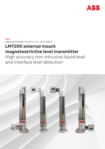
—ME ASURE ME NT & AN AL YT ICS | D AT A SHE ET ABB FSM4000 Electromagnetic flowmeter
Open the catalog to page 1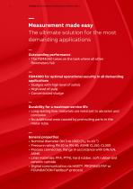
— Measurement made easy The ultimate solution for the most demanding applications — Outstanding performance • The FSM4000 takes on the task where all other flowmeters fail. — FSM4000 for optimal operational security in all demanding applications • Sludges with high level of solids • High level of pulp • Concentrated sludge — Durability for a maximum service life • Long-lasting liner materials are resistant to abrasion and corrosion • No additional wear caused by protruding parts in the meter tube — General properties • Nominal diameter DN 3 to 1000 (¹⁄₁₀ to 40 ”) • Pressure rating PN 10 to PN...
Open the catalog to page 2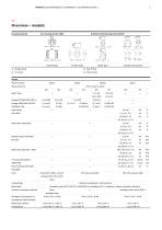
— Overview – models Housing material Fixed Flange Stainless Steel Housing, Series 2000 Fixed Flange Wafer type Variable Connections Sensor Model number Measured error Pipe fitting Wafer type Hard/soft rubber, ceramic ASME BPE External thread ISO 228 / DIN 2999 Liner carbide, PTFE, PFA, ETFE, other Conductivity Electrodes Process connection material ≥ 20 µS/cm (optional ≥ 5/0.5 µS/cm) Stainless steel 1.4571 (316 Ti), 1.4539 (904 L), Hastelloy B-3/C-4, platinum-iridium, tantalum, titanium Steel, stainless steel IP degree of protection in
Open the catalog to page 3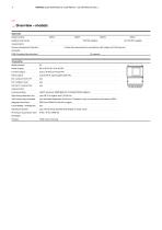
— … Overview – models Approvals Model number requirements Pressure Equipment Directive Conformity assessment in accordance with category III, fluid group 1 Transmitter Model number Power supply Current output Pulse output Forward / reverse flow measurement Communication HART® protocol, PROFIBUS PA®, FOUNDATION Fieldbus® Pipe empty detection std. Self-monitoring, extended yes, extended diagnostic functions / fingerprint only in connection with sensors SE21, diagnosis functions Local display / totalization Density correction yes, manual entry (totalize and display in mass units) IP rating in accordance...
Open the catalog to page 4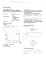
— General data Measuring accuracy Reference conditions in accordance with EN 29104 The grounding of the flowmeter sensor is essential for both safety reasons, and to ensure trouble-free operation of the electromagnetic flowmeter. The ground screws on the flowmeter sensor are to be brought to ground potential. For technical reasons, this potential should be identical to the potential of the metering fluid, if possible. For plastic or insulated lined pipelines, the fluid is grounded by installing ground plates. When there are stray potentials present in the pipeline, we recommend installing a ground...
Open the catalog to page 5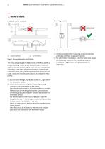
— … General data Mounting position Inlet and outlet sections Figure 5: Mounting position Vertical installation for measuring abrasive materials, preferably with flow in upward direction. B For a horizontal installation, the meter tube must always be completely filled with the measuring medium. Provide for a slight incline of the connection for degassing. A Figure 4: Inlet and outlet section, turn-off devices The measuring principle is independent of the flow profile as long as standing eddies do not extend into the measured value formation, such as may for example occur after double manifolds,...
Open the catalog to page 6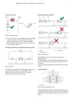
Free inlet or outlet Mounting with pipe vibration Free inflow and outflow For a free outflow, do not install flowmeter at the highest point of the piping or on its outflow side, since the measuring tube may run empty, creating air bubbles. B For free inflow/outflow, provide an invert to make sure that the piping is always full A Mounting with heavily contaminated measuring media 1 Pump 2 Damping device Figure 8: Vibration damping Figure 7: Bypass line For strongly contaminated measuring media, a bypass line in accordance with the figure is recommended so that operation of the system can continue...
Open the catalog to page 7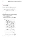
— … General data Installation in piping with larger nominal diameter 1 Reducer Figure 10: Using reducers Determine the resulting pressure loss when using reducers: 1. Determine diameter ratios d/D. 2. .Determine the flow velocity based on the flow rate nomogram (Figure 11). 3. Read the pressure loss on the Y-axis in Figure 11. Figure 11: Flow rate nomogram for flange transition piece at α/2 =
Open the catalog to page 8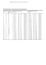
Nominal diameter, nominal pressure, measuring range Nominal diameter Standard DN Min. flow velocity measuring range Max. flow velocity measuring range
Open the catalog to page 9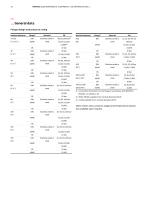
— … General data Flange design and pressure rating Nominal diameter 3 to 25 (¹⁄₁₀ to 1”) steel ASME 1) Connection dimensions for the flange in accordance with DIN2501 / EN1092−1 or ASME or JIS. 2) PN63, PN100 available from nominal diameter DN 25. steel ASME 10 bar Stainless steel or steel steel ASME 3) CL600 available from nominal diameter DN 25. Other meter sizes, pressure stages and temper
Open the catalog to page 10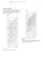
Flow rate nomogram The volume flowrate is a function of the flow velocity and the diameter of the flowmeter. The flowrate nomograph indicates the flowrate range for a specific flowmeter nominal diameter and which flowmeter nominal diameters are suitable for a specific flowrate. Figure 13: Flow rate nomogram, DN 125 to DN 1000 (5 to 40″) Example: Flowrate = 7 m3/h (max. value = range end value). Sensors with nominal diameters DN 20 to DN 65 (¾ to 2½”) are suited for a flow velocity of 0.5 to 10 m/s. 1 Example Figure 12: Flow rate nomogram DN 3 to DN 100 (10 to
Open the catalog to page 11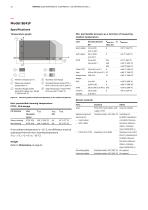
— Model SE41F Specifications Min. permissible pressure as a function of measuring medium temperature Temperature graph Hard rubber Nominal diameter Thick PTFE high 4 Stainless steel flange 2 Measuring medium temperature °C 5 Standard flange (steel): PTFE / PFA / ETFE max. 130 °C (266 °F) 3 Standard flange (steel): Hard/soft rubber max. 90/60 °C (194 to 140 °F) 6 High temperature: thick PTFE / PFA max. 180 °C (356 °F) temperature 1 Ambient temperature °C Figure 14: Measuring medium temperature dependent on the ambient temperature Sensor material Max. permissible cleaning temperature PTFE-, PFA-design...
Open the catalog to page 12All ABB Measurement & Analytics catalogs and technical brochures
 Sensyflow FMT700-P Compact
4 Pages
 CoriolisMaster FCB100, FCH100
60 Pages
 ProKiln GAC400
24 Pages
 AV1 and AV2
24 Pages
 OriMaster FPD500
24 Pages
 AquaProbe FEA200
16 Pages
 FTPA2000-HP260
4 Pages
 266HSH and 266NSH
40 Pages
 261GC, 261GG, 261GN and 261AC
44 Pages
 LM200 Laser level transmitter
24 Pages
 LLT100 Laser level transmitter
26 Pages
 CoriolisMaster FCB400, FCH400
104 Pages
 PME120-AI / PME120-AN (Contrac)
28 Pages
 Millmate roll force systems
20 Pages
 FTSW100 Process software
4 Pages
 Totalflow host software
8 Pages
 SCK
SCK20 Pages
 SCADAvantage™ EFM Tool
4 Pages
 INDI-BOY DSP
8 Pages
 CRANE-BOY / CRANE-BOYP
8 Pages
 9QGPS5100L Tension load cell
12 Pages
 9QGPS4500
8 Pages
 9QGPS3100P
12 Pages
 9QGPS2960
12 Pages
 9QGPS2625
8 Pages
 Ultrasonic level LST400
12 Pages
 MB3600-HP10
5 Pages
 MB3600-CH10
8 Pages
 ACF5000
16 Pages
 Diode laser analyser LS4000
4 Pages
 Magnos28
10 Pages
 Dynamic QR Code
4 Pages
 EL3060
8 Pages
 Pressductor Radial load cells
20 Pages
 HP30
HP304 Pages
 Aztec ATS430
12 Pages
 LMS200
12 Pages
 PGC5000
8 Pages
 LGR-ICOS 927S
4 Pages
 Recording and Control
20 Pages
 2600T Pressure Transmitters
12 Pages
 TZIDC and TZIDC-200
8 Pages
 ProcessMaster FEP610
8 Pages
 ALSCAN Brochure
6 Pages
 MR Series
2 Pages
 Emission Monitoring
8 Pages
 Turbidity Systems 4670 Series
16 Pages
 Sodium Monitor Model 8036
8 Pages
 Aztec 600 Iron Analyzer
12 Pages
 First for Liquid Analysis
16 Pages
 ABB product catalog
32 Pages
 process photometer
6 Pages
 Sodium Monitor Model 8036
8 Pages


- ABB flow meter
- Temperature probe
- ABB volume flow meter
- ABB liquid flow meter
- ABB actuator
- ABB load cell
- ABB measuring instrument
- ABB gas analyzer
- ABB linear actuator
- Automation software solution
- Management software solution
- ABB concentration analyzer
- Chiller
- ABB monitoring analyzer
- ABB electric actuator
- Resistance temperature sensor
- ABB analysis software
- ABB pressure transmitter
- ABB liquids analyzer
- Tension/compression force transducer