
Catalog excerpts
Controlled Switching Buyer's and Application Guide
Open the catalog to page 1
Application, connection and choice: Capacitor banks and Harmonic filters 14 Impact of substation configuration 40 Circuit breakers with mechanically staggerd poles 43 Technical Data: Technical data Shipping data Quality, testing and commissioning Inquiry data 2 Content | Buyer's Guide, Application Guide
Open the catalog to page 2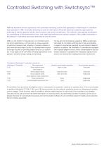
Controlled Switching with Switchsync™ ABB has extensive service experience with controlled switching, and the first generation of Switchsync™ controllers was launched in 1986. Controlled switching is used for elimination of harmful electrical transients upon planned switching of mainly capacitor banks, shunt reactors and power transformers. The method is also gaining acceptance for reenergizing of EHV transmission lines, and replacing traditional pre-insertion resistors. Since 1986, thousands of Switchsync™ controllers have been delivered all over the world. ABB is at the forefront of...
Open the catalog to page 3
Applications Applications The following applications apply to controlled switching: Shunt capacitor banks: Basic aim is to control closing to minimize the energizing transients (voltage transients as well as inrush currents). To improve interrupting performance, controlled opening can also be utilized. Shunt reactors: Basic aim is to control de-energizing to ensure reignition-free behavior. In addition, controlled closing also serves as a useful method for minimizing inrush currents. No-load transformers: The purpose of controlled no-load transformer switching is to minimize the inrush...
Open the catalog to page 4
The strategy for controlled opening is to select arcing times long enough to avoid reignitions at de-energizing. The strategy may vary depending on the size of the shunt reactor. The strategy for controlled closing is to energize at instants resulting in flux symmetry (current symmetry) thereby minimizing the risk for nuisance tripping and rotor vibrations in nearby generators due to zero sequence current. An alternative strategy for controlled energizing is to energize the reactor such that the voltage fronts will be minimized. This will require energizing close to voltage zero and there...
Open the catalog to page 5
Switchsync™ controllers Type of controllers The following five types of controllers are in the product program: E113 E213 F236 L183 T183 The letters indicate basic function: E = standard model for switching at fixed target(s) F = fully equipped model for switching at fixed targets L = special model for switching of uncompensated transmission lines T = special model for switching of power transformers −− First digit in name indicates the number of input commands. − − Second digit indicates the number of adaptive channels or important signals for the function. − − Third digit indicates the...
Open the catalog to page 6
For controllers L183 and T183 the switching instants will vary. The targets will vary depending on the previous interrupting conditions and target for the next making operation is determined by load side voltage measurements. Phase shifts All targets are expressed with respect to a reference time instant, that for all controllers is a busbar voltage zero or, in special applications, a current zero. For controlled closing, the target(s) are defined as a certain phase shift(s) with respect to the reference. For controlled opening, the ultimate targets are certain contact separation instants...
Open the catalog to page 7
Circuit breaker characteristics Single-pole or three-pole operation When a single-pole operated circuit breaker is controlled, a separate output command is given to each pole. Three-pole operated circuit breakers can be arranged with mechanical staggering, making them suitable for controlled switching. In these cases, there will be a built-in mechanical spread (phase shift) between the poles that is appropriate for optimized switching of the load at the specified frequency. The mechanical spread is arranged to reach proper switching conditions with minimum staggering (which for grounded...
Open the catalog to page 8
Control circuit arrangements Fault clearance Since a controlled opening operation will cause an extended clearing time (input check duration, time for finding final reference point and additional waiting time) it is important to arrange all fault tripping commands to by-pass the controller. Substations Different substation arrangements may call for special solutions for overall total functionality. Double circuit breaker schemes and “one-and-a half” circuit breaker schemes (breaker-and-a-half) may require special arrangements for attaining proper function of adaptation control. Trip Circuit...
Open the catalog to page 9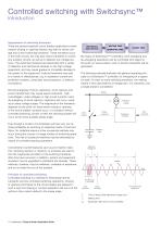
Controlled switching with Switchsync™ Introduction Suppression of switching transients There are several important circuit breaker applications where random closing or opening instants may lead to severe voltage and current switching transients. These transients occur in the main circuits, but may also induce transients in control and auxiliary circuits, as well as in adjacent low voltage systems. The switching transients are associated with a variety of dielectric and mechanical stresses on the high-voltage equipment, and may cause gradual or immediate damage to the system or the...
Open the catalog to page 10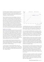
If controlled opening is applied it is important that all protection trip commands, in the event of fault interruptions, are by-passing the controller. In secure mode operation the ”controlled way” is typically extended by about 120 ms at 50 Hz compared to a direct trip command. When the capacitor bank is to be energized, an input command is given to the Switchsync™ controller. Following the command, the controller will determine a reference time instant, related to the phase angle of the busbar voltage. When this has been done, and after an internally created waiting time, the controller...
Open the catalog to page 11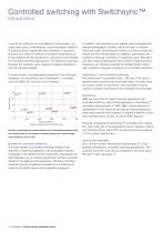
Controlled switching with Switchsync™ Introduction It should be noted that circuit breakers of other design, e.g. using other types of mechanisms, may show larger variations in operating times, statistically from operation to operation, and also as a result of variations in ambient temperature etc. It may therefore be less beneficial to use such circuit breakers for controlled switching applications. The dielectric properties between the contacts, upon making or breaking operations, may also be less suitable. In addition, the controlled circuit breaker itself will experience reduced...
Open the catalog to page 12All ABB AG catalogs and technical brochures
-
 PASS – Plug And Switch System
12 Pages
-
 Transportation
11 Pages
-
 MFM - Multi Functional Modules
16 Pages
-
 Capacitor Bank Controller CQ900
10 Pages
-
 HMC operating mechanism
4 Pages


Archived catalogs
-
 High Voltage Surge Arresters
116 Pages
-
 Gas-insulated Switchgear ENK
8 Pages
-
 Gas-insulated Switchgear ELK-04
32 Pages
-
 PASS M00, PASS M0, PASS M0S
24 Pages
-
 ABB Composite Insulators
24 Pages
-
 Live tank circuit breaker
136 Pages
-
 COMPASS
20 Pages
-
 Disconnecting circuit breakers
12 Pages


