
- Catalogs
- Aavid Thermalloy
- Aavid Clip Attach E Series for BGAs

Aavid Clip Attach E Series for BGAs

Aavid Clip Attach E Series for BGAs
Aavid introduces the Clip Attach E-Series heat sinks designed for BGA applications. These heat sinks feature an easy-to-mount plastic frame with flexible wire springs that resist breakage and enhance thermal contact.
Features & Benefits
- Customizable with various interface materials and finishes.
- Standard finish is black anodize.
- Easy mounting and re-workable.
- Shock and vibration tested.
- Cost-effective solution.
Ordering Information
Part numbers follow the format: EA - XXX - HXXX - XXXX. Example: EA 450 H175 T710.
Specifications
- Keep out zones: 2.5mm for high-density PCB layout.
- Force applied by flexible wire spring.
- No short-circuit concern with UL94V-0 rated PA66.
Product Offerings
Heat sinks are available for various BGA sizes, with specifications for Rca under different air flow conditions (un-ducted, natural convection, ducted). The document provides detailed tables with Rca values for different BGA sizes and heat sink heights.
Mounting Instructions
- Snap plastic tab under one side of BGA substrate edge.
- Rotate to touch BGA and align guiding rods.
- Insert mounting tool and ensure tabs engage BGA edges.
Removal Instructions
- Insert mounting tool from one side, open and lift.
- Slide out from the opposite side and lift the plastic clip.
Global Presence
Aavid provides global support with dedicated engineering resources and distribution partners worldwide.
Catalog excerpts
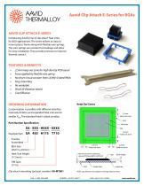
Aavid Clip Attach E Series Aavid Clip Attach E-Series for BGAs AAVID CLIP ATTACH E-SERIES Introducing Aavid’s line of clip attach heat sinks for BGA applications. The series utilizes an easy to mount plastic frame along with flexible wire springs. The wire springs are resistant to breakage and allow for easy installation. They provide pressure to improve thermal contact. FEATURES & BENEFITS » » » » » » » 2.5mm keep out zone for high density PCB layout Force applied by flexible wire spring No short-circuit concern from UL94V-0 rated PA66 Easy mounting Re-workable Shock & Vibration tested Cost Effective ORDERING INFORMATION Customization is possible with different interface materials, finishes, and expanded heat sink size for smaller Rca. The standard finish is black anodize. Part Number Specification EA - XXX - HXXX - XXXX Example Part: E-series Assembled 2.5 mm Keep out zone BGA Size (45mm x 45mm) Heat Sink Height (17.5mm) Minimum 0.3mm clearance, a above PCB board, fter soldered Clip attach mounting tool part number: EA-MT001 Solder Ball NOTE: Specifications are subject to change without notice
Open the catalog to page 1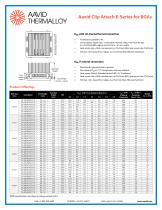
Aavid Clip Attach E-Series for BGAs Flow Direction Parallel to Fin Rca with Un-Ducted forced convection » » » Air direction: parallel to fin Un-Ducted air region size: 3 times BGA nominal width; 1mm from fin top (i.e. 27x27mm BGA, region size 3x27mm = 81mm width) Heat source size = BGA nominal size (i.e. 27x27mm BGA, heat source size 27x27mm) TIM size: 1mm inward for 4 edges. (i.e. 27x27mm BGA, TIM size 25x25mm) Direction: fin perpendicular to ground One value of Rca at 75 °C temperature rise over ambient Heat power (Watts): Adjusted to reach ΔT=75 °C balanced Heat source size = BGA nominal size....
Open the catalog to page 2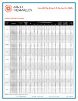
Aavid Clip Attach E-Series for BGAs Product Offerings Continued Heat Sink
Open the catalog to page 3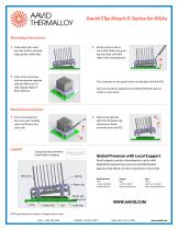
Aavid Clip Attach E-Series for BGAs Mounting Instructions 1. Snap plastic tab under one side of BGA substrate edge, beside solder balls. Rotate another side to touch BGA. Make sure guiding rods align with BGA edge. Insert mounting tool. 3. Close when mounting tool has opened opposite side tab. Make sure all tabs engage edges of BGA substrate. The 2 side tabs on the plastic frame should align with the PCB. Heat sink should be attached to the BGA/PCB firmly and not rotate or move easily. Removal Instructions 1. Insert mounting tool from one side. Carefully open and lift from the same side. Spring...
Open the catalog to page 4All Aavid Thermalloy catalogs and technical brochures
 HydroSink™
4 Pages
 Spotlight LED Heatsink 60W
2 Pages
 LED Heatsink R87-60
3 Pages
 LED Heatsink L100-180
2 Pages
 LED Heatsink L100-270
3 Pages
 LED Heatsink R150-170
2 Pages
 Vicor Bricks
4 Pages
 Half Brick
2 Pages
 Quarter Brick
2 Pages
 Eighth Brick
2 Pages
 SOFTFLEX GAP FILLER
1 Page
 Embedded Solutions
2 Pages
 Standard Products Catalog
116 Pages
 RazorJet™ Series
2 Pages
 Dual Cool Jet
1 Page
 Heat Pipes
6 Pages
 Liquid Cooled Solutions
2 Pages
 HydroSink?
4 Pages
 Brazing Technology
4 Pages


