


GFM

GFM
Catalog excerpts

MASS FLOW METERS Design Features Rigid metallic construction. Maximum pressure of 1000 psig (70 bars). Leak integrity 1 x 10⁻⁹ of helium. NIST traceable certification. Built-in tiltable LCD readout. 0-5 Vdc and 4-20 mA signals. Circuit protection. Can be used as a portable device. Engineering units or 0 to 100% displays. TIO Totalizer option. Metered gases are divided into two laminar flow paths, one through the primary flow conduit, and the other through a capillary sensor tube. Both flow conduits are designed to ensure laminar flows and therefore the ratio of their flow rates is constant. Typical Aluminum GFM Mass Flow Meter A Wheatstone bridge design is used to monitor the temperature dependent resistance gradient on the sensor windings which is linearly proportional to the instantaneous rate of flow. Two precision temperature sensing windings on the sensor tube are heated, and when flow takes place, gas carries heat from the upstream to the downstream windings. The resultant temperature differential is proportional to the change in resistance of the sensor windings. Output signals of 0 to 5Vdc and 4 to 20mA are generated indicating mass molecular based flow rates of the metered gas. Flow rates are unaffected by temperature and pressure variations within stated limitations. General Description Compact, self-contained GFM mass flow meters are designed to read flow rates of gases. The rugged design coupled with instrumentation grade accuracy provides versatile and economical means of flow measurement. Aluminum or stainless steel models with readout options of either engineering units (standard) or 0 to 100 percent displays are available. NIST Traceable Calibration The mechanical layout of the design includes an LCD readout built into the top of the transducer. This readout module is tiltable over 90 degrees to provide optimal reading comfort. It is connected to the transducer by a standard modular plug, and is also readily removable for remote reading installations. www.aalborg.com - e-mail ౧ [email protected] - ( 845.770.3000 - fax 845.770.3010 - Toll Free in U.S.A. and Canada 1.800.866.3837 10
Open the catalog to page 1
MASS FLOW METERS GFM 57, 67 and 77 High Flow Mass Flow Meters NIST Traceable Calibration TABLE 1 - SPECIFICATIONS FOR GFM ACCURACY: ±1.5% of full scale. OPTIONAL ENHANCED ACCURACY: ±1.0% of full scale. Performed at standard conditions [14.7 psia (101.4 kPa) and 70 FF (21.1 FC)] unless otherwise requested. RESPONSE TIME: Generally 2 seconds to within ±2% of actual flow rate over 25 to 100% of full scale. TEMPERATURE COEFFICIENT: PRESSURE COEFFICIENT: MAXIMUM PRESSURE DROP: OUTPUT SIGNALS: Linear 0-5 Vdc. 1000 ohms min. load impedance and 4-20 mA 0-500 Ohms loop resistance.. TRANSDUCER INPUT POWER:...
Open the catalog to page 2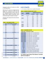
MASS FLOW METERS Transducers without LCD readout are offered for OEM applications. Leak Integrity 1 x 10⁻⁹ smL/sec of helium max to outside environment. GFM mass flow meters are available with flow ranges from 10 mL/min to 1000 L/min N2. Gases are connected by means of 1/4" 3/8" 1/2" compression fittings and 3/4" FNPT fittings. Optional fittings are available. These meters may be used as bench top units or mounted by means of screws in the base. TABLE 3 - MAXIMUM PRESSURE DROP FOR GFM MODEL FLOW RATE [liters/min] MAXIMUM PRESSURE DROP GFM 17 LOW FLOW MASS FLOW METERS TABLE 2 - FLOW RANGES FOR...
Open the catalog to page 3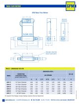
MASS FLOW METERS GFM Mass Flow Meters 2.38 DASHED LINE FOR HIGH FLOW UNITS TABLE 5 - DIMENSIONS FOR GFM DIMENSION (INCH) MODEL CONNECTION Compression Fitting (except model GFM 77) For Specific Flow Ranges Contact Aalborg Customer Service Department. 13 www.aalborg.com - e-mail ౧ [email protected] - ( 845.770.3000 - fax 845.770.3010 - Toll Free in U.S.A. and Canada 1.800.866.3837
Open the catalog to page 4
ORDERING INFORMATION FOR MASS FLOW METERS MODEL MAX FLOW (N2) 10 L/min 17 37 50 L/min 47 100 L/min 57 200 L/min 500 L/min 67 1000 L/min 77 MATERIAL A Aluminum S Stainless Steel Viton® Buna® EPR PTFE / Kalrez® FITTINGS A 1/4" Compression B 1/8" Compression C 1/4" VCR® D 3/8" Compression E 1/2" Compression F 3/4" FNPT G 3/4" Compression H 6mm Compression DISPLAY N No Display L LCD Readout POWER Universal +12 to +26 VDC 6 OUTPUT SIGNAL 0-5 VDC A 4-20 mA B DIGITAL INTERFACE 0 None EXAMPLE: GFM17S-VAL6-A0 5 L/min [N2] 20 psig SPECIFY: FLOW RANGE, GAS and PRESSURE *n.a. = not applicable. GFM17 stainless...
Open the catalog to page 5All Aalborg Instruments catalogs and technical brochures
 Valve catalog
16 Pages
 SMV STEPPING MOTOR VALVES
2 Pages
 DPC
DPC6 Pages
 Rotameter Catalog
74 Pages
 Miniatur-Nadelventil VB
2 Pages
 OPTICAL SENSOR SWITCH O
6 Pages
 TECHNICAL INFORMATION
11 Pages
 CALIBRATIONS
13 Pages
 PTFE-PFA flow meters
2 Pages
 S meter
3 Pages
 T / Tx meter
5 Pages
 P / Px meter
5 Pages
 MASS FLOW CONTROLLERS GFC
5 Pages
 DIGITAL MASS FLOW METER ZFM
6 Pages
 SINGLE TUBE FLOW METERS
5 Pages
 Kits
Kits1 Page
 DFC
DFC8 Pages
 DFM
DFM6 Pages
 XFM
XFM6 Pages
 PWM Paddlewheel meter
1 Page
 Pump Catalog 2015
33 Pages
 In line ptfe flow meter
3 Pages
 SDPROC
4 Pages
 PSV-PSVD
5 Pages
 VX
VX21 Pages
 PWM Paddle Wheel Meter
1 Page
 PWE Paddle Wheel Meter
5 Pages


