
- Catalogs
- Aalborg Instruments
- Digital and Analog Flow Meters Literature


Digital and Analog Flow Meters Literature

Digital and Analog Flow Meters Literature
AALBORG® is a leading manufacturer of precision instrumentation for flow measurement and control, established in 1972. It operates two divisions: the Electronics Division, producing mass flow meters and controllers, and the Variable Area Division, manufacturing rotameters and PFA tube meters. The company is ISO 9001 certified since 1995, emphasizing high-quality products and customer satisfaction.
AALBORG® offers technical assistance and calibration services with equipment traceable to NIST standards. The AALFA-KAL Metrology Laboratory is A2LA accredited, conforming to ISO17025/2005 and Z540-1/1994 standards, providing gas flow calibrations up to 50L/min.
The company provides NIST traceable calibrations for various flow meters and controllers, including those from other manufacturers. The laboratory uses Molboxes and Molblocs for precise calibrations, ensuring compliance with international standards.
GFM mass flow meters are designed for accurate gas flow measurement, featuring a rugged design, built-in LCD readout, and NIST traceable certification. They offer high accuracy and repeatability, available in aluminum or stainless steel models with various output signals.
GFM meters have an accuracy of ±1.0% to ±1.5% of full scale, with a response time of 2 seconds. They operate within a temperature range of 32°F to 122°F and a maximum pressure of 1000 psig. The meters are constructed with materials like anodized aluminum and stainless steel, ensuring durability and leak integrity.
GFM models have varying flow ranges from 10 mL/min to 1000 L/min N2, with maximum pressure drops specified for each model. XFM models also have specified flow rates and maximum pressure drops.
Various power supplies, battery packs, and cables are available for GFM models, with specifications for different regions. Accessories include remote cables, LCD readouts, and mounting kits.
XFM digital mass flow meters support up to 23 engineering units, store calibration data for up to 10 gases, and have programmable totalizers and alarms. They offer user-selectable analog outputs and digital interfaces (RS-232/RS-485, Profibus DP).
The operation involves splitting the gas stream, with a portion passing through a sensor tube. Heat is transferred to the gas, and the temperature differential is measured to determine flow rates. The XFM model incorporates a microcontroller and non-volatile memory for storing calibration data.
The digital interface allows access to internal data and supports automatic sensor zero offset adjustment. The XFM can store calibration data for multiple gases and apply conversion factors via digital commands.
The document lists 23 supported units of measure for flow rate and totalizer data, including user-defined options.
The document specifies environmental conditions, maximum gas pressure, and wetted materials for both aluminum and stainless steel models. It cautions users to select models based on compatibility with the gas being measured.
The document provides technical specifications, dimensions, accessories, and ordering information for Aalborg's Digital Mass Flow Meters, specifically the XFM and ZFM models, as well as the GFC thermal Mass Flow Controllers.
- Specifications: Available in models XFM 17, 37, and 47 with varying dimensions and connection fittings. Supports Profibus capability and offers both LCD and non-LCD versions.
- Accessories: Includes various power supply options and cables for digital communication interfaces.
- Ordering Information: Options for material (Aluminum or Stainless Steel), digital interface (RS232, RS485, PROFIBUS), display type, power supply, output signal, seals, and fittings.
- Design Features: Multi-gas/multi-range functionality, high accuracy, universal power supply, and extensive user programmability. Supports up to 46 engineering units and includes a digital interface with optional Modbus RTU.
- Specifications: Designed for clean gases with a maximum pressure of 1000 PSIG. Offers high repeatability and accuracy with various output signal options.
- Accessories: Includes power supplies, cables, and communication port accessories for enhanced connectivity and functionality.
- Ordering Information: Similar to XFM, with additional options for Modbus interface and different fitting models.
- Design and Operation: Combines accuracy with a compact design for controlling gas flow rates. Utilizes a straight tube sensor and laminar flow paths for precise measurement.
- Principles of Operation: Uses a Wheatstone bridge design to monitor temperature-dependent resistance, providing output signals for mass flow rates.
The document emphasizes the importance of selecting appropriate models based on the specific gas and application requirements, highlighting the responsibility of the customer in ensuring compatibility with the flow media.
- Rigid metallic construction with a maximum pressure of 1000 psig (70 bars).
- Leak integrity of 1 x 10⁻⁹ smL/sec of helium.
- NIST traceable certification and built-in tiltable LCD readout.
- Local or remote setpoint control with 0-5 Vdc and 4-20 mA signals.
- Circuit protection and TIO Totalizer option.
The GFC mass flow controllers are compact, self-contained devices designed to indicate and control gas flow rates. They offer rugged design and instrumentation-grade accuracy, available in aluminum or stainless steel models. The built-in electromagnetic valve allows for precise flow rate settings.
Specifications- Accuracy: ±1.0% to ±3% depending on the model and flow range.
- Repeatability: ±0.25% of full scale.
- Response Time: 2 seconds to within ±2% of actual flow rate.
- Temperature Coefficient: 0.15% of full scale / °C.
- Pressure Coefficient: 0.01% of full scale / psi.
- Maximum Gas Pressure: 1000 psig for certain models, 500 psig for others.
- Turn Down Ratio: 40:1.
- Materials: Aluminum models use anodized aluminum, stainless steel, brass, and Viton® O-rings; stainless steel models use 316 stainless steel and Viton® O-rings.
Flow ranges vary from 10 mL/min to 1000 L/min N2, with different models catering to low, medium, and high flow requirements.
Accessories- Various power supply options for different regions.
- Remote cables and LCD readout options.
- Displays instantaneous, total, and accumulated flow rates with a built-in flow linearizer.
- Supports up to 47 different volumetric and mass flow units.
- Digital RS-232 or RS-485 interface with multi-drop capability.
- Programmable set point table with ramping capability.
- Provides two independent programmable flow totalizers with EEPROM memory backup.
- Programmable alarms and pulse output for flow monitoring.
Supports RS-232 or RS-485 communication with proprietary ASCII software interface and free utility software for configuration and monitoring.
Environmental and Physical Specifications- Operating Temperature: -10 °C to +70 °C.
- Dimensions: 86.4 x 76.2 x 19.1 mm.
- Weight: Approximately 125g.
The document provides detailed information on various power supply kits and digital mass flow controllers (DFC) offered by Aalborg. It includes specifications, features, and ordering information for different models and configurations.
The document lists several GFC flow controller mounting kits with shielded cables and power supplies for different regions. Each kit is specified with its voltage input and output, communication capabilities, and additional features like analog output branches.
The DFCs are programmable devices used to control and monitor gas flow rates. They feature digital signal processing, microprocessor control, and can interface with computers via RS-485 or optional RS-232. Key functionalities include flow set point programming, totalizer functions, auto zero, and multi-gas calibration.
The DFCs have an accuracy of ±1% of full scale, repeatability of ±0.15%, and a response time of 1-2 seconds. They operate within specific temperature and pressure ranges and support various output signals (0-5 VDC, 0-10 VDC, 4-20 mA).
The DFCs support both digital and analog modes, have multi-drop capability, store calibration data for multiple gases, and include features like auto-tune, flow alarms, and gas blending. They also have self-diagnostic tests and programmable flow configurations.
The document lists various cables and power supplies compatible with the DFCs, including options for different regions and interfaces.
Various power supply models are available for different regions, including the UK, US, Europe, and Australia. These models support voltages of 110, 230, and 240 Vac with outputs of ±15 Vdc. They feature either standard or analog interfaces and include LCD jacks.
Table 26 outlines the maximum pressure drop for different DFC models, with values provided in mm H2O, psid, and mbar. For example, the DFC 26 model has a maximum flow of 10 L/min with a pressure drop of 720 mm H2O.
DFC models are available with different flow capacities, materials, and interfaces. They support RS232 and RS485 digital interfaces and offer various input/output signal options. The controllers are designed for precise flow measurement and control.
DFM meters provide data on flow, pressure, and temperature. They can be programmed locally or remotely and support multiple functions such as flow totalizer and alarms. The meters are available in different models with varying flow capacities and support multiple gases and engineering units.
DFM meters have an accuracy of ±1% FS, a pressure range of 5 to 100 psia, and a temperature range of 32°F to 122°F. They offer linear output signals and have built-in protection features. The meters are compliant with CE standards and have a robust construction.
Customers can specify flow range, gas type, and pressure when ordering DFM models. The selection includes options for materials, seals, fittings, and digital interfaces.
AF controllers are designed for indicating and controlling gas flow rates. They feature a straight tube sensor and stainless steel construction, with options for 0-5 Vdc or 4-20 mA signals. The controllers offer high accuracy and leak integrity.
The document provides detailed specifications and operational guidelines for AFC Analog Mass Flow Controllers and SDPROC Microprocessor Driven Command Modules, designed for precise gas flow measurement and control.
- Accuracy: ±1% of full scale at calibration conditions.
- Repeatability: ±0.25% of full scale.
- Response Time: Varies by model, with AFC26 responding in approximately 1 second and AFC36/AFC46 in 2 seconds.
- Temperature and Pressure Coefficients: 0.1% of full scale/°C and 0.01% of full scale/psi respectively.
- Materials: 316 and 416 stainless steel, Viton® O-rings, with optional Buna®, EPR, and Kalrez®.
- Output Signals: Linear 0-5 Vdc or 4-20 mA.
- Flow Control: Utilizes a proportionating electromagnetic valve for precise flow control, unaffected by temperature and pressure variations within specified limits.
- Safety: The valve is normally closed to prevent gas flow during power outages.
- Flow Ranges: AFC models offer flow ranges from 10 mL/min to 100 L/min for nitrogen.
- Functionality: Provides complete control over flow measurement and control functions, with programmable batch and timer flow control capabilities.
- Communication: Standard RS-232 interface with optional Ethernet for remote access and control.
- Display: 24x2 LCD or optional vacuum fluorescent display.
- Alarm and Totalizer Functions: High and low flow alarms, totalizer for gas volume measurement, and programmable actions for alarm conditions.
- Principle: Measures liquid flow by counting electrical pulses generated by a spinning paddle wheel.
- Specifications: Accuracy of ±1% FS, maximum temperature of 60°C, and pressure up to 10 barg.
- Materials: Available in polypropylene and PVDF models, with sapphire jewel bearings for low flow rates.
The Digital Paddle Wheel Flow Meter (PWE) is designed for easy installation and operation, capable of being mounted horizontally or vertically. It features a single moving part and provides flow indication through a transparent acrylic cover. The device offers a versatile square wave flow output signal and is equipped with female NPT ports. It supports multiparameter outputs for flow and temperature, with an optional four-wire platinum RTD. Models are available in polypropylene and chemically resistant PVDF.
The flow meter operates by spinning a paddle wheel as liquid flows through it. Magnets embedded in the paddle generate electrical pulses proportional to the flow rate. The onboard CPU and signal conditioner perform accurate flow and total computation, with digital communication and analog output signals.
The totalizer calculates the total volume of liquid by integrating the flow rate over time. It can be set to zero, started at a preset flow, and programmed to take action at a preset total volume. The main totalizer reading is stored in non-volatile memory, while the pilot totalizer reading is stored in volatile memory.
The PWE flow meters are designed for liquids only, with calibrations performed at standard conditions. They offer a flow accuracy of ±1% of full scale and repeatability of ±0.25%. The liquid temperature measurement range is 34°F to 140°F, with a temperature accuracy of ±0.5°C. The maximum pressure is 10 barg, and the maximum pressure drop is 1.4 bar at 132.5 L/min flow.
The device provides linear 0-5 Vdc or 4-20 mA output signals, with a flow pulse output of 3.3 Vdc amplitude. It supports RS-232 or RS-485 digital interfaces with multi-drop capability. The optional local display includes a 2x16 character LCD with adjustable backlight.
The flow meters are available in various models with different orifice sizes, materials, RTD options, output signals, digital interfaces, seals, and display/keypad configurations. Accessories such as cables and power supplies are available separately.
These meters are constructed of type 316 stainless steel and can be installed in-line. They feature no moving parts, remote electronics mounting, and Aalborg’s proprietary DSP algorithm for noise cancellation and accuracy. The meters provide volumetric and mass flow information, with selectable engineering units and extensive diagnostics.
1. Pipe Requirements: Upstream requires 20 x D and downstream requires 5 x D. Temperature tap is 3.5 x D downstream, and pressure tap is 3.5 x D upstream.
2. Process Connections: ANSI Class 150 RF, 300 RF, 600 RF, Wafer.
3. Electrical Connection: 3/4" FNPT.
4. Ambient Temperature: -12F to 65F (-15C to 149C).
5. Transmitter: Microprocessor-based with a two-line display, programmable for different process variables.
6. Output Signal: Two programmable analog 4-20 mA outputs, two programmable digital optically isolated outputs, and one programmable optically isolated flow pulse output.
7. Enclosure Protection: NEMA 4X with UL, CSA, FM, and KEMA/CENELEC approvals.
8. Power Supply: 15-30 VDC standard, 115 or 230 VAC optional.
1. Flow Meter Selection: Choose style (wafer or flange), meter size, confirm flow ranges, select fluid type, temperature capability, material of construction, mounting connection, and pressure capability.
2. Ordering Information: Specify model, material, display type, power, mounting connection, flange rating, maximum temperature, and fluid type.
1. Flow Rates: Tables provide minimum and maximum flow rates for water, air, and steam at various pressures and temperatures.
2. Pressure Ratings: ANSI flange pressure-temperature ratings are provided for different materials and temperatures.
3. Functional Specifications: Include fluid types, maximum pressure, fluid temperature, low and high flow cut-off, voltage, frequency, and outputs.
1. Flow Rates: Detailed tables for saturated steam, water, and air flow rates at selected pressures and temperatures.
2. Pressure Ratings: Maximum pressure ratings for different flange materials and temperatures.
3. Flange and Wafer Mounting: Specifications for bolt diameter, number of bolts, and dimensions for different meter sizes and flange ratings.
1. Material Selection: Responsibility of the customer; the company accepts no liability.
2. Agency Approval: Contact Aalborg for the status of agency approval.
3. Installation: Vortex meters can be installed in-line using customer-provided or built-in flanges.
The document provides detailed specifications and features of Aalborg's Vortex Multi-Parameter In-Line Flow Meters, designed for accurate flow measurement across various applications.
- Measures temperature, pressure, density, volumetric, and mass flow.
- No moving parts, reducing wear and failure risks.
- Remote electronics mounting up to 100 ft.
- No fluid contact with sensors, preventing clogging.
- High flow turndown ratio of up to 10:1.
- Dual signal processing for improved low flow accuracy.
- Accuracy of 1% of rate with noise cancellation technology.
- Built-in platinum RTD and solid-state pressure sensor.
- Onboard computer for density, volumetric, and mass flow calculations.
- Proprietary DSP algorithm for vortex frequency filtering.
- Extensive diagnostics log with date and time stamps.
- Password-protected data entry and selectable engineering units.
- Two programmable totalizers and digital communication interfaces (RS-232 or RS-485).
- Shedder bar, electrodes, metering tube, and flanges made of 316 SS.
- Electronics housing is epoxy-coated aluminum.
- Mounting positions include vertical, horizontal, and angle.
- Process connections available in ANSI Class 150 RF, 300 RF, 600 RF, and Wafer.
- Flow accuracy of 1% of rate and repeatability of 0.25% of rate.
- Adjustable response time and damping settings.
- Velocity range for liquids and gases provided.
- Temperature measurement range from -4 to 500°F with 0.5°F accuracy.
- Pressure measurement options from 0-100 PSIA to 0-1000 PSIA with 0.5% accuracy.
- Ambient temperature range from -12°F to 149°F.
- Microprocessor-based transmitter with a two-line display.
- Programmable functions for flow, temperature, and pressure alarms.
- Two programmable analog and digital outputs.
- Enclosure protection rated NEMA 4X with various approvals (UL, CSA, FM).
- Power supply options include 15-30 VDC, 115 or 230 VAC.
- Tables provide minimum and maximum flow rates for water, air, and steam at various pressures and temperatures.
- Pressure ratings for different flange materials and sizes are detailed.
- Options for meter size, style (wafer or flange), material, display, power, mounting connection, flange rating, and fluid type.
- Customers must specify fluid name, measuring density, flow rate, temperature, and pressure.
The document provides detailed technical specifications and operational principles for Aalborg's Vortex Insertion Flow Meters, designed for measuring the flow of gases, liquids, or steam in pipes. These meters are constructed from 316 stainless steel and can be inserted into pipes with diameters ranging from 4 inches to 12 feet.
Vortex meters operate by creating vortices as fluid passes around a bluff body. The frequency of these vortices is proportional to the flow rate, allowing for accurate flow measurement. Aalborg's proprietary DSP algorithm enhances measurement accuracy by filtering out non-flow noise.
Key features include a wide range of insertion diameters, installation without line lengthening, optional isolation valves for maintenance without shutting down operations, and no moving parts to wear out. The electronics can be remotely mounted up to 100 feet away, and the system includes extensive diagnostics and password-protected data entry.
The meters support various fluid types, including steam, gas, and liquid, with a maximum pressure of 69 bar (1000 psig) for wafer mounts. They operate within a fluid temperature range of -20°F to 450°F. The system offers a high flow turndown ratio of up to 10:1 and an accuracy of 1% of the rate.
The meters require a power supply of 15-30 VDC or optional 115/230 VAC. They provide two programmable analog 4-20 mA outputs, optically isolated outputs, and digital interfaces (RS-232 or RS-485) with multi-drop capability for up to 255 units.
The flow meters have a flow accuracy of 1% and repeatability of 0.25%. They are designed to operate in ambient temperatures ranging from -12°F to 149°F and are housed in a NEMA 4X enclosure with various agency approvals.
The document includes detailed tables of minimum and maximum flow rates for different pipe sizes and fluid types, as well as pressure ratings for various flange types and materials.
- Sizes and Insertion Depths: The meters are available in various sizes to match pipe diameters ranging from 4" to 144" with corresponding maximum insertion depths from 12" to 36".
- Selection Process: Users must select the meter size based on the internal pipe diameter, confirm flow ranges, select fluid type, temperature capability, material of construction, mounting connection, and pressure capability. Additional data such as fluid viscosity and operating conditions must be provided.
- Model and Options: Models are available with different materials, display options, power supplies, and mounting connections. Flange ratings and maximum temperature capabilities are specified.
- Design Features: These valves offer high leak integrity, metallic construction, and are suitable for both gas and liquid applications with a maximum pressure of 1000 psig.
- Operation Principle: The valves use a variable stroke electromagnetic mechanism to regulate flow rates proportionally to input power. They are normally closed when de-energized and can function as ON-OFF valves.
- Specifications: The valves are available in various sizes with specific flow rates and Cv values. They are constructed from stainless steel and feature Viton® O-rings.
- Functionality: The driver module regulates power to PSV valves using a reference signal. It supports set-point signals of 0-5 Vdc or 4-20 mA and features an auto-select function for input signals.
- Specifications: The module operates with a wide range of power inputs and includes features like polarity protection and a resettable fuse.
- Design Features: These valves offer high precision and resolution for controlling flow rates. They operate continuously without overheating and eliminate coil heating issues.
- Operation: The valves use stepping motors for precise control and are compatible with CMOS logic level signals.
- Specifications: Available in aluminum or stainless steel, these valves handle maximum flow rates of up to 1000 L/min for air and 28 L/min for water.
- Various conversion factors for pressure, length, and temperature are provided to assist in calculations related to the use of these devices.
The document provides a comprehensive overview of various flow measurement and control products manufactured by Aalborg. These include flow meters, mass flow controllers, and valves designed for different applications such as handling corrosive liquids, blending gases, and measuring flow rates in industrial settings.
- Chemically Inert Flow Meters: Designed for low to medium flow of corrosive liquids using PFA flow tubes.
- High Flow Industrial Stainless Steel Flow Meters: Heavy-duty meters with direct reading air and water scales.
- Vortex In-Line and Insertion Flow Meters: Suitable for steam, liquid, and gas services with smart rate and totalizer features.
- Low Cost Mass Flow Controllers: Available in aluminum or stainless with optional LCD readout.
- Digital Mass Flow Controllers: Feature auto zero, totalizer, alarms, and built-in RS485 communication.
- Proportionating Solenoid Valves: Stainless steel valves for controlling gas or liquid flow with pulse width modulation.
- Peristaltic Pumps: Include fixed RPM and variable speed options with flexible tubing.
Authorized repair and service facilities are available in Europe and Asia, providing support for Aalborg thermal mass flow systems.
Catalog excerpts

ooooo &Runm nonocoss koh_ Digital and Analog Flow Meters and rag Controllers FL°W METER OFM
Open the catalog to page 1
Visit our web site at: www.aalborg.com Worldwide Distribution Copyright © 2018 by Aalborg®. All rights reserved. Printed in the United States of America.
Open the catalog to page 2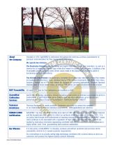
About Founded in 1972, AALBORG®is well-known throughout the world as a primary manufacturer of the Company precision instrumentation for flow measurement and control. We operate two divisions: The Electronics Division produces analog and digital mass flow meters and controllers, as well as a diverse line of wafer and insertion type vortex flow meters for steam, liquid or gases. In addition a line of peristaltic pumps, stepping motor driven valves made in this department are highly useful in processing and OEM applications. The Variable Area Division manufactures a complete line of glass tube...
Open the catalog to page 3
■ cal] ■ gfm] ■ xfm] ■ ZFM ■ gfC ■ tioJ ■ dfC ■ dfm ■ afC Calibrations, Services and Certificates Mass Flow Meters Digital Mass Flow Meters Digital Mass Flow Meters Mass Flow Controllers Totalizer Input/Output Flow Monitor/Controller Digital Mass Flow Controllers Multi-Parameter Digital Mass Flow Meters Analog Mass Flow Controllers www.aalborg.com - e-mail IS! [email protected] - S 845.770.3000 - fax 845.770.3010 - Toll Free in U.S.A. and Canada 1.800.866.3837
Open the catalog to page 4
Paddle Wheel Flow Meters Digital Paddle Wheel Flow Meter Vortex Flow Meters Liquid and Gas Flow Regulators Stepping Motor Valves Conversion Factors Microprocessor Driven Command Modules www.aalborg.com - e-mail ISI [email protected] - ( 845.770.3000 - fax 845.770.3010 - Toll Free in U.S.A. and Canada 1.800.866.3837
Open the catalog to page 5
CALIBRATION, SERVICES AND CERTIFICATES NIST Traceable Calibrations Our laboratories are fully equipped to perform NIST traceable flow calibrations for Rotameters, Mass Flow Meters and Mass Flow Controllers. We offer calibration services on meters and controllers of other manufacturers’ products as well. AALFA-KAL laboratory is equipped to calibrate Molboxes. Our technicians are trained and certified by the manufacturer of Molboxes and Moblocs. For fast cost effective service please contact our customer service department. A2LA Accredited Calibrations AALFA-KAL Metrology Laboratory, division of...
Open the catalog to page 6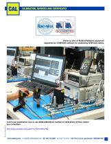
CALIBRATION, SERVICES AND CERTIFICATES Close-up view of Molbox/Molblocs equipment supported by COMPASS software for calibrating GFM flow meters. Link for an explanation how to use Molbox/Molblocs method of calibrations of flow meters and controllers. http://www.youtube.com/watch?v=FVDqrW5y70A www.aalborg.com - e-mail ౧ [email protected] - ( 845.770.3000 - fax 845.770.3010 - Toll Free in U.S.A. and Canada 1.800.866.3837
Open the catalog to page 7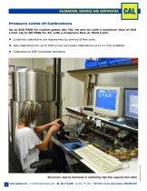
CALIBRATION, SERVICES AND CERTIFICATES Pressure Limits Of Calibrations Up to 500 PSIG for routine gases (Air, N2, He and Ar) with a maximum flow of 250 L/min. Up to 80 PSIG for Air, with a maximum flow of 1000 L/min. n Customer calibrations are represented by primary SI flow units. n Gas calibrations for up to 1000 L/min and water calibrations up to 4 L/min available. n Calibrated to NIST traceable standards. www.aalborg.com - e-mail ౧ [email protected] - ( 845.770.3000 - fax 845.770.3010 - Toll Free in U.S.A. and Canada 1.800.866.3837 Bell prover used by technician in calibrating high flow capacity...
Open the catalog to page 8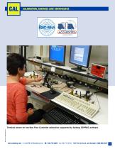
CALIBRATION, SERVICES AND CERTIFICATES Terminal shown for low-flow Flow Controller calibration supported by Aalborg SDPROC software. www.aalborg.com - e-mail ౧ [email protected] - ( 845.770.3000 - fax 845.770.3010 - Toll Free in U.S.A. and Canada 1.800.866.3837
Open the catalog to page 9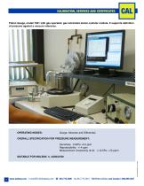
CALIBRATION, SERVICES AND CERTIFICATES Piston Gauge, model 7601 with gas operated, gas lubricated piston-cylinder module. It supports definition of pressure against a vacuum reference. OPERATING MODES: Gauge, Absolute and Differential. OVERALL SPECIFICATION FOR PRESSURE MEASUREMENT: Sensitivity: 0.02Pa +0.5 ppm Reproducibility: +/-4 ppm Measurement Uncertainty (k=2): +/-(0.5Pa + 20 ppm) SUITABLE FOR MOLBOX 1+ A350/A700 BULLETIN EM20180402 CAL www.aalborg.com - e-mail ౧ [email protected] - ( 845.770.3000 - fax 845.770.3010 - Toll Free in U.S.A. and Canada 1.800.866.3837
Open the catalog to page 10
CALIBRATION, SERVICES AND CERTIFICATES Our gas calibration laboratory has NIST traceable approved in-house equipment to certify our calibration devices. Molbox/Molblocs based calibration for GFC Flow Controller. Our technicians are trained and certified and our Laboratory is equipped to calibrate Molboxes. In addition, our laboratory can calibrate NIST traceable approved “In-House” equipment to certify our primary calibration devices. We also calibrate and certify customers’ Molboxes. For fast cost effective service please contact our customer service department. www.aalborg.com - e-mail ISI...
Open the catalog to page 11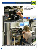
CALIBRATION, SERVICES AND CERTIFICATES Gas flow calibration laboratory is capable of performing calibrations from 1 mL/min to 1000 L/min at 21.1 FC /101.325 kPa (70 FF, 14.69 PSI abs). www.aalborg.com - e-mail ౧ [email protected] - ( 845.770.3000 - fax 845.770.3010 - Toll Free in U.S.A. and Canada 1.800.866.3837 According to “state of the art” calibrating practices, calibrations are performed based on 4 to 1 uncertainty rat
Open the catalog to page 12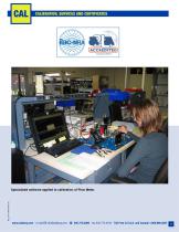
CALIBRATION, SERVICES AND CERTIFICATES Specialized software applied to calibration of Flow Meter. www.aalborg.com - e-mail ౧ [email protected] - ( 845.770.3000 - fax 845.770.3010 - Toll Free in U.S.A. and Canada 1.800.866.3837
Open the catalog to page 13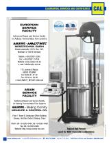
CALIBRATION, SERVICES AND CERTIFICATES EUROPEAN SERVICE FACILITY Authorized Repair and Service Facility for Aalborg Thermal Mass Flow Systems aalborg MESSTECHNIK GMBH Klosterrunsstraße 18 P.O. Box 1321 Müllheim D-79379 Germany Telefon: +49 (0)7631 5545 Fax: +49 (0)7631 14740 Website: www.analyt-mtc.de e-mail: [email protected] 175, avenue d’Alsace 68000 COLMAR Tel: 03 89 41 47 78 Fax: 03 89 41 59 88 e-mail: [email protected] ASIAN SERVICE FACILITY Authorized Repair and Service Facility for Aalborg Thermal Mass Flow Systems aalborg - Beijing Comity MEASURE & CONTROL CO. Floor 1 Tower B Jindayuan...
Open the catalog to page 14All Aalborg Instruments catalogs and technical brochures
 Valve catalog
16 Pages
 SMV STEPPING MOTOR VALVES
2 Pages
 DPC
DPC6 Pages
 Rotameter Catalog
74 Pages
 Miniatur-Nadelventil VB
2 Pages
 OPTICAL SENSOR SWITCH O
6 Pages
 TECHNICAL INFORMATION
11 Pages
 CALIBRATIONS
13 Pages
 PTFE-PFA flow meters
2 Pages
 S meter
3 Pages
 T / Tx meter
5 Pages
 P / Px meter
5 Pages
 MASS FLOW CONTROLLERS GFC
5 Pages
 DIGITAL MASS FLOW METER ZFM
6 Pages
 SINGLE TUBE FLOW METERS
5 Pages
 Kits
Kits1 Page
 DFC
DFC8 Pages
 GFM
GFM5 Pages
 DFM
DFM6 Pages
 XFM
XFM6 Pages
 PWM Paddlewheel meter
1 Page
 Pump Catalog 2015
33 Pages
 In line ptfe flow meter
3 Pages
 SDPROC
4 Pages
 PSV-PSVD
5 Pages
 VX
VX21 Pages
 PWM Paddle Wheel Meter
1 Page
 PWE Paddle Wheel Meter
5 Pages


