
- Catalogs
- 2VV s.r.o.
- Regulation

Regulation

Regulation
The RB control unit is designed for controlling VCP industrial air curtains and devices with voltage-controlled fans and heaters. It offers three-level fan speed control, remote operation with light indication, and a 36-month guarantee. It operates at 12 V, suitable for indoor environments with temperatures from -5 °C to +40 °C and humidity up to 90%. The unit's IP rating is IP55, while the controller's is IP20.
Available in two models: RB1-7A and RB3-4A, with power supplies of 230/50 V/Hz and 400/50 V/Hz, respectively. Maximum fan current is 7.0 A for RB1-7A and 4.0 A for RB3-4A. Both models have an IP55 rating and dimensions of 240 x 310 x 110 mm.
The unit can be installed on a wall or device in horizontal or vertical positions. Ensure adequate airflow to prevent overheating and provide maintenance access. Mount using screws and wall plugs, avoiding flammable materials within 100 mm.
Includes a regulator and remote controller connected by a data cable. Features buttons for ON/OFF, fan speed, and heater output with light indication. Indicators for door position and cleaning intervals are included. Operation depends on connected devices and accessories like thermostats and door contacts.
Adjusts fan speed and controls the ZV-3 zone valve for water flow. Up to 10 ZV-3 valves can be connected. Automatic valve control requires a TER-K or TER-P thermostat. Connects to anti-freeze sensors and timers.
Adjusts fan speed and activates heaters using STYKAC-20-LC2 contactors. Automatic control requires a thermostat. Supports aftercooling of electric heaters and connects to timers.
Adjusts fan speed and controls the ZV-3 zone valve for water flow, with up to 10 valves connected. Automatic control requires a thermostat.
Adjusts fan speed and controls the ZV-3 zone valve. Anti-freeze protection requires a PO switch, SERVO-LF230 servo drive, and RB-S relays. Timers can be connected.
Adjusts fan speed and activates heaters using contactors. Automatic control requires a thermostat. Connects to a servo drive and timers.
Includes setting cleaning intervals, RS 485 communication, phase loss protection, and potential-free contact operation indication. Up to six regulators can be controlled with a single controller.
Required accessories include a three-way valve with a servo drive.
Components and accessories for controlling heating systems include three-way valves, contactors, and connection cables. The three-way valve controls water heater output, while the STYKAC-20-LC2 contactor switches electric heaters. Connection cables are available in standard and custom lengths, up to 50 meters.
Installation instructions emphasize proper airflow around controllers to prevent overheating. Controllers should be mounted on walls or switchboards, ensuring easy maintenance access. Wiring diagrams are indicative; actual assembly should follow product nameplate ratings and diagrams.
Specifies IP ratings for controllers, indicating protection levels against solid particles and water. Provides guidelines for installation environment, such as temperature and humidity limits. Recommended power supply cable cross-section is detailed in the instruction manual.
Required and optional accessories include sensors and thermostats for temperature control. Details the use of duct-type and wall-mounted sensors, as well as controllers for adjusting temperatures. Accessories ensure correct operation of heating systems.
Primary parameters for controllers include power supply specifications, current load ranges, and temperature setting ranges. The RV3-25/P controller supports three-phase heaters up to 25 kW and offers a 36-month guarantee. Adjusts output based on room or duct temperature requirements.
Guidelines stress ensuring free airflow and avoiding flammable materials near controllers. Control options vary based on connected accessories, with trimmers available for setting temperatures. Output control can be managed via a 0-10 V interface for precise regulation of heater output.
Outlines specifications for the OSMU mixing unit controller and the SMU mixing unit. The OSMU controller manages the heating water mixing process based on required air temperature. Operates on a power supply of 1 x 230 V AC / 50-60 Hz with a setting range for air temperature from 0 to 35 °C. Housed in a grey plastic casing with an IP 65 rating.
Controller should be installed in sheltered, dry indoor areas with ambient temperatures between 0 °C and +40 °C. Mounted on a wall or switchboard, ensuring door accessibility for maintenance. No flammable materials should be within 100 mm of the controller. The SMU mixing unit can be installed in any position and must be connected to heat exchanger tubes using flexible hoses. For temperatures above 90 °C, heat-resistant cables are required.
The OSMU controller requires at least one temperature sensor, with options for duct-type or wall-mounted sensors. The SMU mixing unit requires a control device to manage operation, with pump rotational speed adjustable via a switch on the pump motor housing.
Essential accessories include temperature sensors for the OSMU controller and a separate controller for the SMU mixing unit if not directly connected to a control device.
Wiring diagrams are indicative; installation should follow nameplate ratings and diagrams affixed to or enclosed with the product.
The SMU mixing unit is designed for water temperatures between -10 °C and +110 °C and pressures not exceeding 1.0 MPa. Includes components such as closing valves, a mixing valve with a servo-actuator, flexible hoses, thermometers, seals, and a pump. The mixing valve has specific leakage parameters, and components have varying IP protection ratings.
Provides a coding key for identifying different models of the SMU mixing unit and their specifications, such as pump pressure and mixing valve kVS values.
Technical specifications and installation guidelines for valves and controllers in water-type air heating systems. Covers thermostatic valves, zone valves, mixing valves, and speed controllers, detailing features, installation requirements, and operational parameters.
Controls heating water in accordance with VDI 2035. Installed in dry indoor areas with temperatures between +5 °C and +60 °C. Controls water temperatures from 0 °C to +90 °C and pressures up to 0.1 MPa. Includes a DN25 fitting and a thermostatic head with a 2 m capillary.
Controls heat output of water-type heat exchangers, suitable for standalone heaters and those in ventilation units. Operates within a water temperature range of 0 °C to +110 °C and pressures up to 1.0 MPa. Features a three-way design with a servo drive and an IP 40 rating.
Motorized 3-way mixing valve with bypass for similar applications as the ZV3, with a water temperature range of +2 °C to +110 °C. Allows for up to 50% glycol in water. Has an IP 50 rating.
Designed for asynchronous motors, reducing fan speed to control air capacity. Supports single-phase and three-phase models, with a maximum load of 7 A. Installed in dry indoor areas with temperatures from 0 °C to +40 °C and has an IP 40 rating.
Devices require installation in sheltered, dry indoor environments with specific temperature ranges. Proper installation should allow for maintenance access, and electrical cables must not touch valve surfaces. Control is typically achieved through switches or thermostats, with wiring diagrams provided for guidance.
No special accessories are required for proper operation, though optional thermostats are available. Wiring diagrams in the catalog are indicative; actual assembly should follow product nameplate ratings and enclosed instructions.
Outlines specifications for controllers and sensors in HVAC systems. The RO speed controller is for asynchronous motors, available in single-phase and three-phase models, with a loading capacity of up to 7 A / 230 V and 9 A / 400 V. It has an IP40 rating. The CKT duct-mounted temperature sensor measures air temperature in HVAC systems, with a range of 0 to 50°C and an IP55 rating. The CPT room temperature sensor measures indoor air temperature, with a range of 0 to 30°C and an IP20 rating. The CPTO temperature controller can function as a room air temperature sensor and controller, with a range of 0 to 30°C and an IP20 rating. The AS-CO2-EE80-20 and AS-CO2-EE85-20 sensors measure CO2 concentration with a range of 0 to 2000 ppm, operational temperature from -20 to 60°C, and an output voltage of 0-10V DC. The CI-EE80-2CT3/T55 and CI-EE85-2C32 sensors also measure CO2 concentration, using infrared principles for long-term stability, with similar operational parameters. The CI-LCN-FTK140VV sensor measures relative humidity with an output voltage of 0-10V DC, operational temperature from -20 to 70°C, and an IP65 rating. The CI-PS 1003 motion sensor detects heat emissions with a 90° detection angle and a range of 12 meters, resistant to animals up to 25 kg.
Controllers can be installed in any position, ensuring sufficient access for maintenance and keeping flammable materials at least 100 mm away. Wiring diagrams are indicative; installation should follow product nameplate ratings and diagrams.
The ROxA and ROxB controllers use a rotary switch to adjust speed in five levels, with ROxB also featuring START and STOP buttons. External switches and motor thermal contacts can be connected to the controller.
No special accessories are required for operation, but optional accessories like a door switch are available.
Wiring diagrams are provided for reference, with recommended cable cross-sections detailed in the instruction manual.
Provides coding keys for identifying different models and types of controllers and sensors, such as RO for speed controllers and CTK for duct sensors.
- Motion Sensor: Detection range of 12m, 90° angle, low noise PIR sensor, resistant to animals under 25 kg, installation height between 1.8 to 2.2m, operating temperature from -10°C to +50°C, signal output of 1NC/1C 60V DC, 300mA.
- Anti-Freeze Sensor (PO): Temperature range of +2 to +20°C, maximum contact load of AC 230V/24A, IP43 rating, ambient temperature from -50 to +70°C.
- Capillary Thermostat (TER-K): Measures air temperature, range 0 to 40°C, IP44 rating, maximum sensor temperature of +120°C.
- Room Thermostat (TER-P): Temperature range of +5 to +30°C, IP20 rating, maximum contact load of AC 250V/16A.
- Timer (SH-TM-848): Weekly schedule, supply voltage 230V/50Hz, switching capacity 16A, IP rating not specified.
- Door Switch (DS): IP67 rating, switching capacity 6A, 230V.
- Door Contact (DK): Switching capacity 30mA, 12V.
- Servo Drive (SERVO/TD-04-230-1): Controls HVAC flaps, torque 4Nm, IP54 rating.
- Flexible Hose (OH): Stainless steel with thermal insulation, temperature range -20 to +110°C, maximum pressure 1 MPa.
- Motion sensors should be installed on walls or corners at specified heights, avoiding environments with high temperature fluctuations.
- Anti-freeze sensors should be installed behind water exchangers in clean air systems.
- Thermostats should be used to monitor and control air temperature, ensuring they are installed in appropriate environments.
- Timers should be securely fixed to DIN strips in switchboards.
- Door switches and contacts should be installed to control equipment based on door positions.
- Servo drives should be installed in dry indoor areas, ensuring proper positioning and connection.
- Flexible hoses should be used for easy connection of exchangers, ensuring proper length and connection size.
- Ensure all sensors and devices are used within their specified temperature and pressure ranges.
- Follow installation guidelines to maintain device integrity and functionality.
- Regular maintenance and cleaning are recommended to prevent sensor malfunction.
- Wiring diagrams are indicative; always refer to product-specific diagrams for installation.
Catalog excerpts

Regulation Regulation
Open the catalog to page 1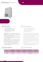
BASIC FEATURES – Thee-level fan speed control – For single-phase and three-phase fans – Controls both water and electric heaters – Bedienung des Wasser- und Elektroerhitzers – Remote controller with light indication The RB control unit is designed primarily for controlling the Das Steuergerät RB ist primär für die Bedienung von In- VCP industrial air curtains. In addition, the unit may also be dustrieluftschleier VCP bestimmt. Mit der Regelung können used for controlling devices comprising the voltage controlled weiter Anlagen mit einem spannungsgeregelten Ventilator und fan and water or electric...
Open the catalog to page 2
– Both control unit and controller are installed to a wall or to – Der Regler und die Bedienung werden an die Wand oder a device being controlled in a horizontal or vertical position. an die betätigte Anlage in senkrechter oder waagerechter – Free air ow shall be ensured around the unit to avoid overheating safe distances shall be kept, see gure. Position installiert – um Überhitzung des Gerätes zu vermeiden, um sie Luft – Installation of the unit shall allow a sufcient access for per- strömen - es sind die Abstände, siehe Abbildung einzuhalten forming maintenance, servicing, and dismounting...
Open the catalog to page 3
The control unit comprises a regulator and remote controller Das Steuergerät besteht aus dem Regler und Fernbedienung, connected to the regulator by a light-current data cable. The der zum Regler mit einem Schwachstrom-datenkabel ange- remote controller includes the ON/OFF button, button for set- schlossen ist. Auf der Fernbedienung bendet sich die Taste ting the fan speed, and button for adjusting the water/electric EIN/AUS, die Taste für die Drehzahleinstellung des Ventilatores, heater output. All buttons are tted with a light indication. In Taste für die Einstellung der Leistung Wasser-/Elektroerhitzers....
Open the catalog to page 4
INDESSE with electric exchanger The remote controller can be used for setting the fan speed Von der Fernbedienung kann die Ventilatordrehzahl eingestellt and activating the heaters in two output levels using the und der Erhitzer mit den Schützen STYKAC-20-LC2 geschaltet STYKAC-20-LC2 contactors. The control unit is tted with a werden. Das Steuergerät hat die Betätigungsphase für die control phase for contactors of the 1 and 2 heating level. Two Schütze der 1. und 2.Heizungsstufe. An jede können parallel contactors can be connected in parallel to each of them. The zwei Schütze angeschlossen werden....
Open the catalog to page 5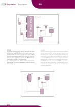
The remote controller can be used for setting the fan speed Von der Fernbedienung kann die Ventilatordrehzahl eingestellt and switching the ZV-3 zone valve that supplies water to the und das Zonenventil ZV-3, welches das warme Wasser in den exchanger or returns it back to the heat source. Up to 10 ZV-3 Wärmetauschern einläßt oder zurück zur Wärmequelle bringt valves can be connected in parallel to the control unit. Automatic umgeschaltet werden. Zum Steuergerät können parallel bis three-way valve control requires either the TER-K duct-type 10 Ventile ZV-3 angeschlossen werden. Für die automatische...
Open the catalog to page 6
Assembly ap, fan, and water heater Zusammenbau – Klappe, Ventilator und Wasser-wär- The remote controller can be used for setting the fan speed and switching the ZV-3 zone valve that supplies water to the Von der Fernbedienung kann die Ventilatordrehzahl eingestellt exchanger or returns it back to the heat source. Up to 10 ZV-3 und das Zonenventil ZV-3, welches das warme Wasser in den valves can be connected in parallel to the control unit. Wärmetauschern einläßt oder zurück zur Wärmequelle bringt Automatic three-way valve control requires either the TER-K umgeschaltet werden. Zum Steuergerät...
Open the catalog to page 7
Common features for all connection types - Setting the cleaning interval indicated on the panel - Possibility to connect to the master control system via RS - Phase loss protection - Indication of device operation by a potential-free contact - Possibility of controlling up to six regulators using single controller chaining Gemeinsame Funktionen fur alle Anschlusstypen - Einstellung des am Pult signalisierten Reinigungsintervalls - Mbglichkeit des Anschlusses an das iibergeordnete Steuer- system Liber das Protokoll RS 485 - Ausfallschutz einer Phase - Signalisierung des Anlagenlaufes - Mbglichkeit...
Open the catalog to page 8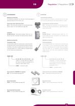
Required accessories Erforderliches Zubehör The following accessories are required to take advantage of Dieses Zubehör ist zu bestellen, ansonsten wird es nicht mög- the basic features of the control unit. lich sein die Grundfunktionen des Steuergerätes zu nutzen. Three-way valve with servo drive ZV-3 – three-way valve necessary for controlling the water ZV-3 – Dreiwegventil erforderlich, für die Steuerung der heater output. For more details see page 308 Leistung des Wasserwärmetauschers. Nähere Besch-reibung auf Seite 308 istance load 20 A, necessary for switching electric heaters. schluß-widerstand...
Open the catalog to page 9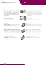
Switching relay RB-S – switching relay for controlling the shutting RB-S – Schaltrelais für die Betätigung der Schließklappe ap or indicating the unit operation. The same relay oder Anzeige des Gerätelaufes. Das gleiche Relais in connected in a different way is used for controlling anderem Anschluss wird zur Betätigung des Zonenven- the zone valve when the anti-freeze protection is ac- tils bei der Schaltung des Gegenfrostschutzes genützt. tivated. If the shutting ap and anti-freeze protection Sofern die Schließklappe und der Gegenfrostschutz are connected, two relays are required to ensure a...
Open the catalog to page 10
WIRING DIAGRAMS Control unit with the ELEKTRISCHE SCHALTPLANE
Open the catalog to page 11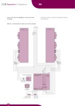
Control unit with the air curtain and water Steuergerat mit dem Luftschleier mit Wasser- exchanger warmetauscher three-way zone valve external control door switch externe Steuerung Turkontakt
Open the catalog to page 12All 2VV s.r.o. catalogs and technical brochures
 AIR CURTAINS
4 Pages
 Components
78 Pages
 Heating Units
16 Pages
 Heat Recovery Units
46 Pages
 Ventilation units
92 Pages
 Air Curtains - 2VV
96 Pages
 Introduction
22 Pages
 Regulation_technical catalogue
72 Pages
 Components_technical catalogue
68 Pages


Archived catalogs
 Air curtains_technical catalog
116 Pages
