
- Catalogs
- 2VV s.r.o.
- Components

Components

Components
- Basic Features: Available in wall-mounted and duct configurations with impeller diameters of 200, 250, and 300 mm, featuring automatic thermal protection and an IP 42 rating.
- Installation: Recommended horizontal axis installation using 4 screws for wall-mounted fans and duct installation for CLC-P.
- Control: No integrated speed control; speed adjusted by reducing supply voltage, not compatible with frequency converters.
- Dimensions and Performance: Detailed specifications include dimensions, weight, voltage, current, input power, RPM, airflow volume, and operating temperature.
- Basic Features: Available in wall-mounted and duct configurations with impeller diameters of 300 to 630 mm, featuring automatic thermal protection, IP 44 rating, and a 36-month guarantee.
- Installation: Can be installed in any position, with horizontal axis recommended, using 4 screws.
- Control: Similar to CLASSIC fans, no integrated speed control; speed adjusted by reducing supply voltage, not compatible with frequency converters.
- Dimensions and Performance: Detailed specifications include dimensions, weight, voltage, number of phases, RPM, airflow volume, current, input power, operating temperature, protection class, and insulation class.
Catalog excerpts

Components Komponenten
Open the catalog to page 1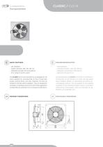
Components Komponenten CLASSIC / CLC-N BASIC FEATURES – wall installation – integrated automatic thermal protection – integrierter automatischer Wärmeschutz – IP 42 rating for electric system The CLASSIC CLC-N wall-mounted fans are designed for the Die Wandventilatoren CLASSIC CLC-N sind für den Betrieb in indoor operation for conveying fresh air free of rough dust, Innenräumen, für den Transport von reiner Luft ohne groben grease, chemical fumes, and other impurities. The fans are Staub, Fettigkeit, Dämpfe von Chemikalien und weiterer Ver- suitable for the stand-alone installation. They are...
Open the catalog to page 2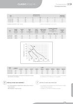
! The level of acoustic pressure in free space was measured on the intake * Der Pegel des akustischen Drucks im Freiraum wurde an der Ansaugseite side of the fan in lm distance. des Ventilators in einer Entfernung von 1 m gemessen. INSTALLATION AND ASSEMBLY ¥ INSTALLATION UND MONTAGE It is recommended to install the fan with an axis in the ho- - die Installation des Ventilators wird mit der Achse in waage- rizontal position. rechter Stellung empfohlen Wall installation using 4 screws - Installation an die Wand mit 4Stiick Schrauben
Open the catalog to page 3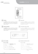
CLASSIC / CLC-N Components Komponenten The CLASSIC CLC-N fans are not tted with an integrated Die Ventilatoren CLASSIC CLC-N haben keine integrierte speed control system. The fan speed is controlled by redu- Drehzahlregelung. Die Drehzahlregelung wird durch Senkung cing the supply voltage. The fans cannot be controlled by a der Speisespannung durchgeführt, eine Regelung mit Fre- frequency converter. quenzwandler ist nicht möglich. WIRING DIAGRAMS ELEKTRISCHE SCHALTPLÄNE The CLASSIC CLC-N fans are not tted with an integrated Die Ventilatoren CLASSIC CLC-N haben keine integrierte speed control...
Open the catalog to page 4
VULKAN / VKN-N Components Komponenten BASIC FEATURES – Wall installation – Integrated automatic thermal protection – Integrierter automatischer Wärmeschutz – IP 44 rating for electric system The VULKAN VKN-N wall-mounted fans are designed for the Die Wandventilatoren VULKAN VKN-N sind für den Betrieb indoor operation for conveying fresh air free of rough dust, in Innenräumen, für den Transport von reiner Luft ohne gro- grease, chemical fumes, and other impurities. The fans are ben Staub, Fettigkeit, Dämpfe von Chemikalien und weiterer suitable for the stand-alone installation. They are designed...
Open the catalog to page 5
Airflow volume [rrf.h"1] / Luftmenge [rrf.Sf]
Open the catalog to page 6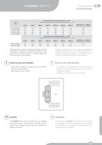
VULKAN / VKN-N Components Komponenten Sound pressure level in frequency bands Lp OCT [dB] Pegel des akustischen Drucks in den Frequenzbändern Lp OCT [dB] 125 Hz With lter A, LpA1m [dB(A)] Laut Filter А, LpA1m [дБ(А)] Sound power level in frequency bands Lw OCT [dB] Pegel der akustischen Leistung in den Frequenzbändern Lw OCT [dB] 125 Hz With lter A, LwA [dB(A)] Laut Filter А, LwA [дБ(А)] The level of acoustic pressure in free space was measured on the intake side of the fan in 1m distance in accordance with DIN 45635. The level of sound power was measured in accordance with DIN 45635. In order...
Open the catalog to page 7
VULKAN / VKN-N Components Komponenten Recommended speed controller types Empfohlene Typen von Drehzahlreglern Type ROV-E, ROV-D Typ ROV-E, ROV-D Optional accessories Wählbares Zubehör Speed controller RO – for more details see page 321 RO – nähere Beschreibung auf Seite 321 Speed controller ROV-xx – for more details see page 316 ROV-xx – nähere Beschreibung auf Seite 316 WIRING DIAGRAMS ELEKTRISCHE SCHALTPLÄNE All the wiring diagrams included in the catalogue are only in- Sämtliche im Katalog angeführten Schaltpläne sind nur informativ. formative. When assembling the product, observe strictly...
Open the catalog to page 8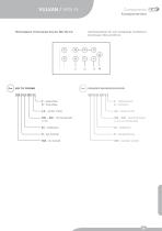
VULKAN / VKN-N Wiring diagram of three-phase fans dia. 500, 630 mm Components Komponenten Anschlussschema für eine dreiphasige Ventilatoren Durchmesser 500 und 630 mm
Open the catalog to page 9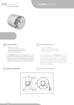
Components Komponenten CLASSIC / CLC-P BASIC FEATURES – Installation into a duct – Integrated automatic thermal protection – integrierter automatischer Wärmeschutz – IP 42 rating for electric system The CLASSIC CLC-P duct fans are designed for the indoor Die Rohrleitungsventilatoren CLASSIC CLC-P sind für den operation for conveying fresh air free of rough dust, grease, Betrieb in Innenbereichen, für den Transport von reiner Luft chemical fumes, and other impurities. The fans are suitable for ohne groben Staub, Fettigkeit, Dämpfe von Chemikalien und installation into HVAC ducts and for other...
Open the catalog to page 10
CLASSIC / CLC-P Components Komponenten Operation temperature [°С] Betriebstemperatur [°C] Airow volume max. [m3/h] Luftmenge [m3/St] Protection class Schutzart * The level of acoustic pressure in free space was measured on the intake side of the fan in 1m distance. * Der Pegel des akustischen Drucks im Freiraum wurde an der Ansaugseite des Ventilators in einer Entfernung von 1 m gemessen. – It is recommended to install the fan with an axis in the ho- – die Installation des Ventilators wird mit der Achse in waage- rizontal position. – Installation into a duct rechter Stellung empfohlen – Einbau...
Open the catalog to page 11
CLASSIC / CLC-P Components Komponenten The CLASSIC CLC-P fans are not tted with an integrated Die Ventilatoren CLASSIC CLC-P haben keine integrierte speed control system. The fan speed is controlled by redu- Drehzahlregelung. Die Drehzahlregelung wird durch Senkung cing the supply voltage. The fans cannot be controlled by a der Speisespannung durchgeführt, eine Regelung mit Fre- frequency converter. quenzwandler ist nicht möglich. WIRING DIAGRAMS ELEKTRISCHE SCHALTPLÄNE All the wiring diagrams included in the catalogue are only in- Sämtliche im Katalog angeführten Schaltpläne sind nur informativ....
Open the catalog to page 12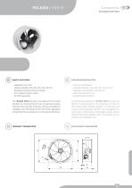
VULKAN / VKN-P Components Komponenten BASIC FEATURES – Installation into a duct – Integrated automatic thermal protection – integrierter automatischer Wärmeschutz – IP 44 rating for electric system The VULKAN VKN-P duct fans are designed for the indoor Die Rohrleitungsventilatoren VULKAN VKN-P sind für den operation for conveying fresh air free of rough dust, grease, Betrieb in Innenbereichen, für die Förderung von reiner Luft chemical fumes, and other impurities. The fans are suitable for ohne groben Staub, Fettigkeit, Dämpfe von Chemikalien und installation into HVAC ducts and for other HVAC...
Open the catalog to page 13All 2VV s.r.o. catalogs and technical brochures
 AIR CURTAINS
4 Pages
 Regulation
86 Pages
 Heating Units
16 Pages
 Heat Recovery Units
46 Pages
 Ventilation units
92 Pages
 Air Curtains - 2VV
96 Pages
 Introduction
22 Pages
 Regulation_technical catalogue
72 Pages
 Components_technical catalogue
68 Pages


Archived catalogs
 Air curtains_technical catalog
116 Pages
