カタログの抜粋

XI'AN SHELOK INSTRUMENT COMPANY LIMITED 1.Pressure Transmi�er 4.Dead Weight Tester 7.Temperature Transmi�er 2.Pressure Gauge 5. Level Transmi�er 8.Density Meter
カタログの1ページ目を開く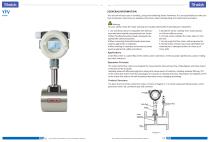
GENERALINFORMATION This manual will assist you in installing, using and maintaining Vortex Flowmeter. It is ourresponsibility to make sure that all operators have access to adequate instructions about safeoperating and maintenance procedure. For your safety, review the major warnings and cautions below before operating your equipment. 5.Handle the sensor carefully. Even smallscratches or nicks can affect accuracy. 6. For best results calibrate the meter atleast 1 time per year. 7. Do not purge the flow meter withcompressed air. 8. During Vortex removal, liquid may spill.Follow the...
カタログの2ページ目を開く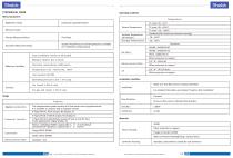
Shelok TECHNICAL DATA Measuring System Application range Reference Condition Operating Condition
カタログの3ページ目を開く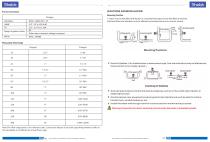
Mounting Positions * Avoid Air Bubbles. If air bubbles enter a measurement pipe, flow rate indications may be affecled and measurement errors maybe caused.+j Valve Avoiding Air Bubbles ★ Avoid all pipe locations where the flow is pulsating, such as in the outlet side of piston or diaphragm pumps * Avoid locations nearequrpment producing electrical interference such as electric motors, transformers, variable frequency, etc. * Install the meterwith enough room for future access for maintenance purposes A Warning; Precaution for direct sunshine and rain when the meter is installed outside....
カタログの4ページ目を開く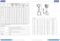
DIN PN16 Flange Meter Dimensions Note: For model with temperature and pressure compensation,the flowmeter lenath should beincreased 50mm compared to the value (A)in table above. Wafer Connection
カタログの6ページ目を開く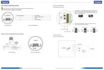
CAUTIONS FORINSTALLATION Terminal Board of V Type Warning: Electrical Hazard Disconnect power before beginning wiring HGVF-N: Pulse Output, Explosion Proof Model Terminal Symbols Terminal Configuration If the signal is interfered at working site, please try to short the terminals as following drawing(a). After *a" step, if the situation is not improved, please short the terminals as drawing(b) no ■ HGVF-A:Two-wire 4-20mA Output, No Local Display Terminal Symbols Wiring Descriptionu (1)2 wire 4-20mA output Terminal Wiring
カタログの7ページ目を開く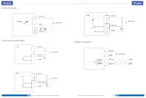
(3) Pulse Output/ Scaled Pulse Output
カタログの8ページ目を開く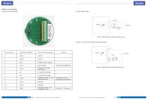
HGVF-D. Local Display Wire Terminal Description 2 wire 4-20mA output 3 wire 4.2 0 mA current output wiring instructions. 3 wire 4 .20mA burrent output wiring di_gr_m
カタログの9ページ目を開く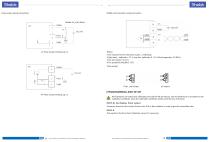
Pulse output wiring instructions RS485 communication wiring instruction oC Pulse output wiring di_gr_m Notice: l.The requirement for the pulse output _s following: 2.High level _.mplitude > 2 2 V; Low lvel mplitude< 0.8 V :Pulse frequenby< 3 0 00 Hz 3.The lod resistor< 5 0 0 o. 4.The protobolis MoDBUS . RTU Pulse output. PROGRAMMING AND SETUP PP Pulse output wiring di_gr_m All flowmeters are tested and calibrated prior before left the factory, and the keyK-factor is provided on the calibration certificate. Keep the calibration certificate wellto avoid the loss of K.factor HGVF-N+ No...
カタログの10ページ目を開く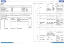
Note: It will display"0000"before input password.lf the password is incorrect, it will go toPl menu automatically under un-settable status.
カタログの12ページ目を開く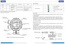
Fl_me proof shell Extern_l autton l.Press short time The nrst short time press will displ_y the bommunib_tion p_r_meters _nd the soft-w_re version numaer. 2 . Press long time when extern_l ble_r funbtion set to "0", it will shut down the ble_r funbtion . when extern_l ble_r funbtion set to "1", the nrst time long press( over 3s), the v_lue will reset . lf long press _g_in _fter the nrst long press menu, the tot_l go to zero, _nd return to the m_in menu; if no oper_tion for 100s, it will return to m_in menu _utom_tib_lly. when extern_l ble_r funbtion set to "2", the tot_l now will ae reset...
カタログの14ページ目を開く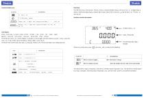
Shelok Symbols Function display area Unit display There _re 14 units _v_il_ale, n_mely _s m31h , m31min , L1h , Llmin , tlh , tlmin , kglh, kglmin , US G_l1h , US G_l1min , UK G_l1h , UK G_l1min , ft3lh , ft3lmin The third line is now r_te, _nd the middle r_w bould h_ve seven digits with three debimj pl_bes _t most , when the now r_te _re aig ,it exbh_nge to the debim_l displ_y digits _utom_tib_lly The fourth line is bommunib_tion sign, w_rning sign, Temper_ture, Pressure bompens_tion settng sign etb Total Flow The nfth line is tot_l now symaol . The tot_l now b_n douale direbtion displ_y,...
カタログの15ページ目を開く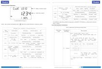
Password interface introductions DV type ft ow tr nsmitter p s sword setting form lntrodubtions: when the p_ssword is wrong, you b_n bhebk PI. P41 sbreen p_r_meters, aut b_nnot set the p_r_meters . User menu parameters introductions Flow transmitter password setting form
カタログの16ページ目を開く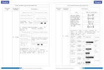
Fl ow tra nsmi tter passw ord s etti ng f orm Fl ow tra nsmi tter passw ord s etti ng f orm Functions code Functions code D es cripti on T emperature setting T e mp er at ur e a bn or mi ty U nder working condition Under Temper_ bompens_ tion ture _ lgorithm Temperature abnormity situation T em pe ra tu re h i dd en V a lue display and the fouth line display U nder working c ondition algorithm Under presssure c o mp en sa ti on algorithm The fourth line b_ n displ_ y ń ow unit , Communib_ tion symaol , Al_ rm symaol , when the pressure or temper_ bompens_ ting , displ_ y T or P, when one is...
カタログの17ページ目を開く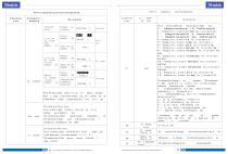
Shelok Flow transmitter password setting form Functions code Parameters meaning Description Algorithm selebt The n fth line is displ_ yed tot_ 1 n ow, 1 0 . digits v_ lid digit displ_ y , displ_ y up to three debim_ 1 pl_ bes , Autom_ tib_ lly switbh debim_ 1 displ_ y digits when the n ow r_ te is 1_ rge Divided into three lines he n rst line is displ_ yed the a_ ttery volt_ ge , n ow perbent_ ge or burrent v_ lue The sebond line is displ_ yed the origin_ 1 frequenby v_ The third line is displ_ yed n xed frequenby or sign_ 1 strength da, Switbhed ay " R1 GHT” Divided into two lines The n...
カタログの18ページ目を開く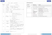
TROUBLESHOTTING Symptom
カタログの19ページ目を開く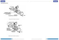
Installation Bolts Flow FMnge-Sl^le Flow Meter ln&tellal<Crv
カタログの20ページ目を開くXi'an Yunyi Instrument Co.のすべてのカタログと技術パンフレット
-
 K series
3 ページ
-
 YX-2006B
2 ページ
-
 XY-2002
1 ページ
-
 YFM4800E
14 ページ
-
 YD32
YD322 ページ
-
 Deadweight tester JY
2 ページ
-
 Mass flow meter Coriolis
14 ページ
-
 Orifice flow meter
6 ページ
-
 Mass flow meter
3 ページ
-
 Vortex flow meter YFV
20 ページ
-
 Turbine flow meter YFT
13 ページ
-
 Mass flow meter YFT300D
13 ページ
-
 Turbine flow meter
13 ページ
-
 Liquids level gauge
3 ページ
-
 Radar level sensor
12 ページ
-
 YD31 series
4 ページ