カタログの抜粋
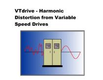
VTdrive - Harmonic Distortion from Variable Speed Drives
カタログの1ページ目を開く
Introduction to Harmonics Symptoms Expected Harmonics from VFD’s Harmonic Resonance Understanding IEEE519-1992 Harmonic Solutions for VFD’s
カタログの2ページ目を開く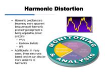
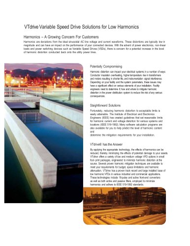
Harmonic Distortion • Harmonic problems are becoming more apparent because more harmonic producing equipment is being applied to power systems – VFD’s – Electronic Ballasts – UPS • Additionally, in many cases, these electronic based devices can also be more sensitive to harmonics Effective Grounding Harmonic Solutions Surge Solutions Voltage Variation Solutions
カタログの3ページ目を開く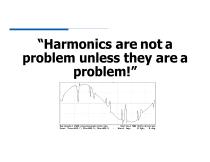
problem unless they are a Horizontal 2500 microseconds/digision Vertical 500 Uolts/division Urns: Preu=610.7, Min=605.5, Max=605.5 - Uorst Inp= H Upk, 0 deg
カタログの4ページ目を開く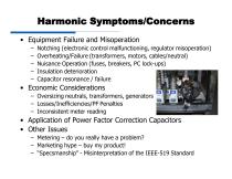
Harmonic Symptoms/Concerns • Equipment Failure and Misoperation – – – – – Notching (electronic control malfunctioning, regulator misoperation) Overheating/Failure (transformers, motors, cables/neutral) Nuisance Operation (fuses, breakers, PC lock-ups) Insulation deterioration Capacitor resonance / failure • Economic Considerations – Oversizing neutrals, transformers, generators – Losses/Inefficiencies/PF Penalties – Inconsistent meter reading • Application of Power Factor Correction Capacitors • Other Issues – Metering – do you really have a problem? – Marketing hype – buy my product! –...
カタログの5ページ目を開く
Expected Harmonics Source Typical Harmonics* Arcing Devices Transformer Energization * Generally, magnitude decreases as harmonic order increases
カタログの6ページ目を開く
Harmonic Spectrum Harmonic magnitude (per unit) 0.2 0.14 • Normal VFD Harmonic Spectrum – Lower harmonic orders have the higher magnitudes – Magnitudes should decline as the harmonic order increases
カタログの7ページ目を開く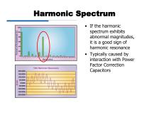
Harmonic Spectrum spectrum exhibits abnormal magnitudes, harmonic resonance interaction with Power Factor Correction
カタログの8ページ目を開く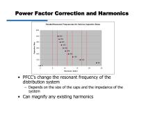
Power Factor Correction and Harmonics Parallel Resonant Frequencies for Various Capacitor Sizes Harmonic Order • PFCC's change the resonant frequency of the distribution system - Depends on the size of the caps and the impedance of the • Can magnify any existing harmonics
カタログの9ページ目を開く
Power Factor Correction and Harmonics HARMONIC NUMBER Reactors can be added to the PFCC bank to create a tuned filter - Tuned to a 'non-characteristic' harmonic (i.e. 4.7th) Becomes a sink for 5th harmonic currents
カタログの10ページ目を開く
IEEE 519 - 1992 • It is currently the only recognized industry standard in North America for setting harmonic limits (voltage and current) • Designed to limit utility harmonics as well as customer harmonic contribution to the utility grid • Standard ONLY applies to the Point of Common Coupling (PCC) – The point where the utility connects to multiple customers – If a utility transformer is provided, the PCC is most likely on the LINE side of the transformer IEEE 519 is widely misunderstood and misapplied in the industry
カタログの11ページ目を開く
IEEE 519 – Point of Common Coupling (PCC) Possible POA’s (Customer Side) (Utility Side) Only place that IEEE 519 applies ??? = Linear loads for % current distortion dilution
カタログの12ページ目を開く
Harmonic Calculators File Help General System Special Applications XFMR Filter Total HP of Linear Load
カタログの13ページ目を開く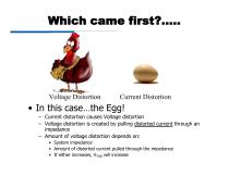
Which came first?….. Voltage Distortion Current Distortion • In this case…the Egg! – Current distortion causes Voltage distortion – Voltage distortion is created by pulling distorted current through an impedance – Amount of voltage distortion depends on: • System impedance • Amount of distorted current pulled through the impedance • If either increases, VTHD will increase
カタログの14ページ目を開く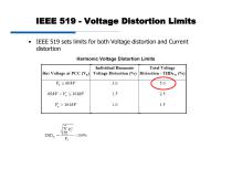
IEEE 519 - Voltage Distortion Limits IEEE 519 sets limits for both Voltage distortion and Current Harmonic Voltage Distortion Limits
カタログの15ページ目を開く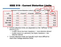
IEEE 519 - Current Distortion Limits Not THD Harmonic Current Distortion Limits (Ih and TDD) in % of IL (≤ 69kV) • Current distortion limits are dependent on the “stiffness” of the source (Isc/IL) – A stiffer source has lower impedance = more distortion allowed – A softer source (i.e. generator) has higher impedance = less distortion allowed • Current distortion limits are typically much more difficult to reach than Voltage distortion limits
カタログの16ページ目を開く
THD vs. TDD • THD(I)= Total Harmonic Current Distortion – Measured distortion on actual instantaneous current flowing – “Sinewave Quality Factor” • Lower the % THD, the closer the current waveform is to a true sinewave – Not used anywhere in IEEE 519 THD = 80% Is this acceptable? Depends on system full load, % linear load, etc.
カタログの17ページ目を開く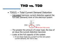
THD vs. TDD • TDD(I) = Total Current Demand Distortion – Calculated harmonic current distortion against the full load (demand) level of the electrical system Full load of the system – The greater the amount of Linear load, the less of an issue the current distortion becomes – Looks at the full capacity of the system • If non-linear loads are a small % of the full system current demand, the TDD is less
カタログの18ページ目を開く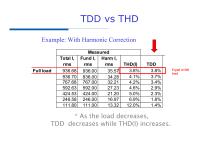
TDD vs THD Example: With Harmonic Correction Full load * As the load decreases, TDD decreases while THD(I) increases. Equal at full load
カタログの19ページ目を開く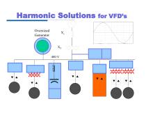
Harmonic Solutions for VFD’s Oversized Generator Active Filter Blocking Filter Isolation Transformer Tuned Filter Phase Shift Transformers
カタログの20ページ目を開く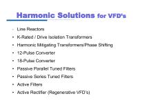
Harmonic Solutions for VFD’s * Line Reactors • K-Rated / Drive Isolation Transformers • Harmonic Mitigating Transformers/Phase Shifting • 12-Pulse Converter • 18-Pulse Converter • Passive Parallel Tuned Filters • Passive Series Tuned Filters • Active Filters • Active Rectifier (Regenerative VFD’s)
カタログの21ページ目を開く
Line Reactors • Line Reactor = Inductor • An inductor slows down the rate of rise of current. Current • Impedance of an inductor increases as frequency increases • Reactors have more impedance the higher the harmonic order
カタログの22ページ目を開く
Effect of Drive Line Reactors
カタログの23ページ目を開く