カタログの抜粋

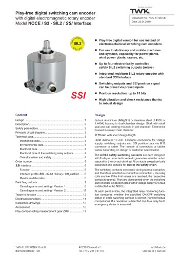
Play-free electronic digital switching cam encoder with electromagnetic absolute encoder / CANopen Model NOCN Play-free version for use instead of electromechanical switching cam encoders For use in stationary and mobile machines and systems, particularly for wind turbines, power plants, cranes, etc. Up to six electronically controlled switching outputs consisting of - Relay: Changeover contacts - PhotoMOS: Normally open/closed contacts Integrated absolute multiturn encoder with CANopen interface Parameterisable via CANopen bus High vibration and shock resistance thanks to the robust design Option: SIL2 certificate (Datasheet NOC13099) Velocity signal via CANopen Further available versions: CANopen safety: Datasheet NOC13099 SSI: Datasheet NOC12555 SSI - SIL2: Datasheet NOC 14199 Analog: Datasheet NOC12393 - Robust housing manufactured from seawater-proof aluminium (AlMgSi1) or stainless steel (material: 1.4305 optionally 1.4404). - Shaft fitted with ball bearings bears the magnet for recording the angular position and the drive gear of the multiturn transmission for absolute revolution counting. - Shaft and transmission are located in the prechamber. Sealed off from this, the main chamber contains all electronic components for position recording, evaluation and output. - Available Versions: Ø 58 mm with different flange and shaft designs. 2 x relay and 2 x PhotoMOS at maximum. Ø 64 mm (standard) with clamping collar and M6 threaded holes plus two device connectors. 2 x relay and 2 x PhotoMOS at maximum. Ø 120 mm (optional) with clamping collar, M6 threaded holes and synchroniser groove. 4 relays at maximum. 79 mm with short housing length. Ø • 4 x relay • 4 x relay and 2 x PhotoMOS (on request) - Electrical connection for voltage supply, switching out puts and CANopen data via M12 connectors or cables. The number of connectors or cables varies depending on version or customer specifications. TWK-ELEKTRONIK GmbH Heinrichstrasse 85
カタログの1ページ目を開く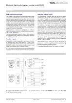
Electronic digital switching cam encoder model NOCN Description General functional principle Switching outputs (cams) This involves a play-free electronic switching cam encoder (abbreviated to: NOCN) with a maximum of four galvanically separated switching outputs (cams), which can be set by the customer and which are activated or deactivated depending on the relevant position of the drive shaft. A parameterisable multiturn absolute encoder with CANopen interface plus the switching cam encoder printed circuit board with separate controller are integrated into the compact housing. The...
カタログの2ページ目を開く
Electrical data ■ Sensor system: ■ Operating voltage range: ■ Power consumption: ■ Resolution: ■ Measuring range: ■ Meas. step deviation: ■ Absolute accuracy: ■ Repeatability: ■ Output code: ■ Code path: ■ Temperature drift: ■ Reference value: ■ Overvoltage protection and galvanic separation with CANopen bus ■ CAN interface: ■ Address setting: ■ Terminating resistor: ■ Max.transmission length: ■ EMC standards: Interference emission: Interference immunity: ■ Electrical connection: ■ CAN IC voltage rating: ASIC with HALL elements + 11 VDC to + 28 VDC < 2.5 W 4096 steps / 360° - (12-bit) or...
カタログの3ページ目を開く
Electronic digital switching cam encoder model NOCN Technical data Environmental data Operating temperature range: Storage temperature range: Resistance: - 40 °C to + 85 °C - 45 °C to + 85 °C 250 m/s², 6 ms, 100 x each in 3 axes 100 m/s², 5 Hz ... 2000 Hz, 1 h each in 3 axes (Higher values optional) IP67, optionally IP69K Switching output relay electrical data Maximum switching current: Maximum switching voltage: 60 VDC / VAC Note: The effective maximum voltage is dependent on the connector into which the switching contacts are integrated: M12, 12-pin: max. 30 VDC, M12, 8-pin:...
カタログの4ページ目を開く
^ Standard version Electrical and mechanical variants N CANopen Galvanic separation 1. See page 6: V1 -VS1 CAN_GND 1screening/housing ^ Recommended V2 -VS = CAN_GND 1screening/housing V3 -VS = CAN_GND = screening/housing Electrical connections (see remark on page 11, 12): ^ Combine kind (S, T, K, L) and number of desired connection 1 = 1 connection 2 = 2 connections 3 = 3 connections S Via device connector M12, radial T Via device connector M12, axial (at NOCN79 only on request) K Via cable, 1 m 2, radial 2 other lengths possible L Via cable, 1 m 2, axial (at NOCN79 only on request) C2...
カタログの5ページ目を開く
Find details on page 11 Order code number, remarks V1: This version provides complete galvanic separation. Power supply and CAN_GND is galvanically separated. The housing and the screening of the cable is galvanically separated as well. The screening of the cable comes to the housing of the NOCN via the housing of the mating plug. V2: This version provides partly galvanic separation. Power supply and CAN_GND are not galvanically separated. The housing and the screening of the cable are galvanically separated from power supply and CAN_GND. The screening of the cable comes to the housing of...
カタログの6ページ目を開く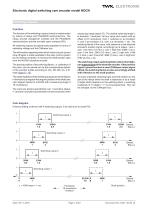
Switching outputs Function The function of the switching outputs (cams) is implemented by means of relays and PhotoMOS semiconductors. The relays provide changeover contacts and the PhotoMOS semiconductors provide normally open contacts (NO). All switching outputs are galvanically separated in terms of operating voltage and the CANopen bus. The information regarding when which relay is to pick up and drop off again is made available to the relay control system by the internal controller. If receives the shaft position data from the NOCN's absolute encoder. The precise position of the...
カタログの7ページ目を開く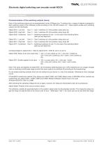
Electronic digital switching cam encoder model NOCN Switching outputs Parameterisation of the switching outputs (cams) Each of the switching outputs can be parameterised via the CANopen bus. To achieve this, a range of objects is assigned to each switching output in the CANopen profile according to CiA, DS 406 revision 4.01. These objects enable each switching output to be set individually: Object 6310: Low limit Cam 1 > Cam 1 switches on in this position (relay picks up) Object 6320: High limit Cam 1 > Cam 1 switches off in this position (relay drops off) Object 6330: Hysteresis Cam 1 >...
カタログの8ページ目を開くTWK-ELEKTRONIK GmbHのすべてのカタログと技術パンフレット
-
 Rotary encoder TBN58/C3
22 ページ
-
 Rotary encoder TBD
12 ページ
-
 Rotary encoder TBE58
16 ページ
-
 Rotary encoder KRP
7 ページ
-
 Rotary encoder TBN50/C3
22 ページ
-
 Product range 2022
64 ページ
-
 Image brochure TWK
28 ページ
-
 Inclinometer NBA51
6 ページ
-
 Rotary encoder TBA42
16 ページ
-
 Rotary encoder TRA42
16 ページ
-
 Rotary encoder TRN58/C3
22 ページ
-
 Manual TRN50/C3
86 ページ
-
 Rotary encoder TRN50/C3
22 ページ
-
 Rotary encoder TRN42/C3
22 ページ
-
 Rotary encoder TBN42/C3
22 ページ
-
 Rotary encoder TRE58
16 ページ
-
 Rotary encoder TRT
14 ページ
-
 Vibration sensor NVA
12 ページ
-
 Inclinometer NBN
17 ページ
-
 Inclination sensor NBT
10 ページ
-
 Inclinometer NBA
17 ページ
-
 Inclinometer NBN/S3 SIL2
13 ページ
-
 Rotary encoder TBE50
16 ページ
-
 Rotary encoder HBE
14 ページ
-
 Rotary encoder TRK
11 ページ
-
 Rotary encoder TMN50
6 ページ
-
 Rotary encoder TRE42
6 ページ
-
 Rotary encoder TRE50
6 ページ
-
 Rotary encoder TRA50
6 ページ
-
 Rotary encoder TBE42
6 ページ
-
 Rotary encoder TME42
6 ページ
-
 Rotary encoder TRD
12 ページ
-
 Rotary encoder TME50
6 ページ
-
 Rotary encoder TBN36
6 ページ
-
 Rotary encoder TMA50
6 ページ
-
 Rotary encoder TMN42
6 ページ
-
 Rotary encoder TMA42
6 ページ
-
 Rotary encoder TBA50
16 ページ
-
 Rotary encoder TBE36
6 ページ
-
 Rotary encoder TBN42
6 ページ
-
 Rotary encoder TBN37
8 ページ
-
 Rotary encoder TBA37
7 ページ
-
 Rotary encoder TBB50
16 ページ
-
 Rotary encoder PBA12
2 ページ
-
 Rotary encoder TBA36
6 ページ
-
 Rotary encoder TKA60
2 ページ
-
 Rotary encoder TKN46
7 ページ