カタログの抜粋
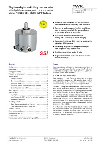
Play-free electronic switching cam encoder with electromagnetic rotary encoder Model NOCI / S3 - SIL2 / incremental interface Preliminary data sheet Play-free version for use instead of electromechanical switching cam encoders use in stationary and mobile machines For and systems, especially for power plants, wind power plants, cranes, etc. to four electronically controlled Up safety SIL2 switching outputs (relays) Integrated multiturn SIL2 rotary encoder with standard incremental interface Switching outputs can be preset via preset input Internal position resolution up to 15 bits High vibration and shock resistance thanks to robust design Robust aluminium (AlMgSi1) or stainless steel (1.4305 or 1.4404) housing in dual-chamber design. Shaft with shaft seal and ball bearing mounted in pre-chamber. Electronics housed in sealed main chamber. TWK-ELEKTRONIK GmbH Bismarckstraße 108 Ø 79 mm with short design length Shaft diameter 12 mm. Electrical connection for voltage supply, switching outputs and incremental position data via M12 connector or cable. The number of connectors or cables varies depending on design or customer specification. The 4 SIL2 safety switching contacts are each designed with 2 relays connected in series to guarantee reliable contact separation (no contact sticking). All contacts are galvanically separated and suitable for use in the safety chain. The switching contacts are closed during normal operation, and therefore establish a conductive connection - the relay coils are live. If the limit values are reached, the respective contact is opened. They are also opened when the switching cam encoder is not connected to the voltage supply or a fault is detected in the NOCI through self-diagnosis. At each point in time, the integrated relay monitoring function compares whether the specified ON/OFF switching status of each switching contact is correct (nominal/actual comparison). If a deviation is detected due to a relay fault, failsafe status is assumed. info@twk.de visit
カタログの1ページ目を開く
Electronic switching cam encoder - model NOCI / S3Description General functional principle This involves a play-free electronic switching cam encoder (abbreviated to: NOCI) with a maximum of four galvanically separated1’ SIL2 switching outputs that can be set by the customer, and which are activated or deactivated depending on the respective position of the drive shaft. A parameterisable multiturn absolute encoder with incremental interface as well as the four switching outputs are integrated in the compact housing. The switching outputs can be preset. A special shaft design appropriate to...
カタログの2ページ目を開く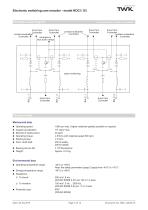
Electronic switching cam encoder - model NOCI / S3 Principle circuit diagram drive from drive from Controller Controller contact evaluation Controller emergency shut down relays 2 contacts shown. A total of 4 available drive from Controller contact evaluation Controller drive from Controller contact evaluation Controller drive from Controller drive from Controller relay monitoring Technical data Mechanical data Operating speed: 1000 rpm max. (higher rotational speeds possible on request) 105 rad/s² max. Moment of inertia (rotor): 20 gcm² Operating torque: ≤ 8 Ncm (with rotational speed 500...
カタログの3ページ目を開く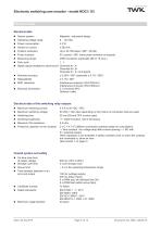
SUPREME SENSORING Technical data Electrical data ■ Sensor system: ■ Operating voltage range: ■ Power consumption: ■ Switch-on current: ■ Position resolution: ■ Pulse numbers: ■ Measuring range: ■ Duty cycle: ■ Signal outputs (resistant to short-circuit): ■ Absolute accuracy: ■ Repeatability: ■ EMC standards: ■ Electrical connection: Magnetic - redundant design 9 ... 30 VDC < 3 W < 500 mA Up to 32,768 steps / 360° (15 bits) 512 pulses / 360° (other pulse numbers on request) 4096 revolutions (optionally 256 or 16 revs.) 1 : 1 Channels A+, A-Channels B+, B-Channels Z+, Z- (null signal) ± 0.25%...
カタログの4ページ目を開く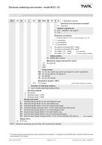
SUPREME SENSORING Order number ^ Standard version Electrical and mechanical variants* 01 Standard Output / signal level: D HTL - definition: see page 6 U TTL - '' Electrical connection: ^ Combine type (S, T, K or L) and number (1, 2, 3) 1 = 1 connection 2 = 2 connections 3 = 3 connections S Via device connector M12, radial T Via device connector M12, axial# K Via cable 1 m**, radial (# on request) L Via cable 1 m**, axial# (** other lengths possible) Safety profile: S3 Safety SIL2 version Measuring range (relevant for cams): 16 Revolutions 256 '' Pulse tracks: A+, A-, B+ and B- as well as...
カタログの5ページ目を開く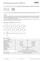
Electronic switching cam encoder - model NOCI / S3Order number - mating connector M12, 4-pin, socket: STK4GS60 Function To register and output the angle or position of the shaft precisely, the contactless electromagnetic sensor system is equipped with an incremental interface so that the measured variable is available as digital data. The incremental signal is generated from the previously registered absolute position signal. This position signal, which corresponds to the precise position of the shaft, is also used to actuate the switching outputs. This model's measuring range is set to...
カタログの6ページ目を開く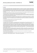
Electronic switching cam encoder - model NOCI / S3 Switching outputs Function The function of the switching outputs is implemented using relays. Two relays are connected in series per switching output. This measure significantly increases reliable separation of the contacts, even if one relay does not separate (contact sticking). In terms of operating voltage and the incremental output signal, the contacts are galvanically1) separated. The relay monitoring function detects whether a relay contact is open or closed as specified by the controller - i.e. whether it has the required switching...
カタログの7ページ目を開く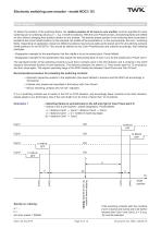
Electronic switching cam encoder - model NOCI / S3 Cam diagrams Preset point: in the centre of the switching flanks To define the position of the switching flanks, the relative position of all cams to one another must be specified for each switching cam on ordering (values a, b → e.g. in shaft revolutions). With the Cam Preset function, all switching flanks are shifted en bloc without changing their position relative to one another. The desired preset position in the switching flank ensemble is located at the current shaft position (in this example, the middle of the ensembles or, in the...
カタログの8ページ目を開くTWK-ELEKTRONIK GmbHのすべてのカタログと技術パンフレット
-
 Rotary encoder TBN58/C3
22 ページ
-
 Rotary encoder TBD
12 ページ
-
 Rotary encoder TBE58
16 ページ
-
 Rotary encoder KRP
7 ページ
-
 Rotary encoder TBN50/C3
22 ページ
-
 Product range 2022
64 ページ
-
 Image brochure TWK
28 ページ
-
 Inclinometer NBA51
6 ページ
-
 Rotary encoder TBA42
16 ページ
-
 Rotary encoder TRA42
16 ページ
-
 Rotary encoder TRN58/C3
22 ページ
-
 Manual TRN50/C3
86 ページ
-
 Rotary encoder TRN50/C3
22 ページ
-
 Rotary encoder TRN42/C3
22 ページ
-
 Rotary encoder TBN42/C3
22 ページ
-
 Rotary encoder TRE58
16 ページ
-
 Rotary encoder TRT
14 ページ
-
 Vibration sensor NVA
12 ページ
-
 Inclinometer NBN
17 ページ
-
 Inclination sensor NBT
10 ページ
-
 Inclinometer NBA
17 ページ
-
 Inclinometer NBN/S3 SIL2
13 ページ
-
 Rotary encoder TBE50
16 ページ
-
 Rotary encoder HBE
14 ページ
-
 Rotary encoder TRK
11 ページ
-
 Rotary encoder TMN50
6 ページ
-
 Rotary encoder TRE42
6 ページ
-
 Rotary encoder TRE50
6 ページ
-
 Rotary encoder TRA50
6 ページ
-
 Rotary encoder TBE42
6 ページ
-
 Rotary encoder TME42
6 ページ
-
 Rotary encoder TRD
12 ページ
-
 Rotary encoder TME50
6 ページ
-
 Rotary encoder TBN36
6 ページ
-
 Rotary encoder TMA50
6 ページ
-
 Rotary encoder TMN42
6 ページ
-
 Rotary encoder TMA42
6 ページ
-
 Rotary encoder TBA50
16 ページ
-
 Rotary encoder TBE36
6 ページ
-
 Rotary encoder TBN42
6 ページ
-
 Rotary encoder TBN37
8 ページ
-
 Rotary encoder TBA37
7 ページ
-
 Rotary encoder TBB50
16 ページ
-
 Rotary encoder PBA12
2 ページ
-
 Rotary encoder TBA36
6 ページ
-
 Rotary encoder TKA60
2 ページ
-
 Rotary encoder TKN46
7 ページ