カタログの抜粋

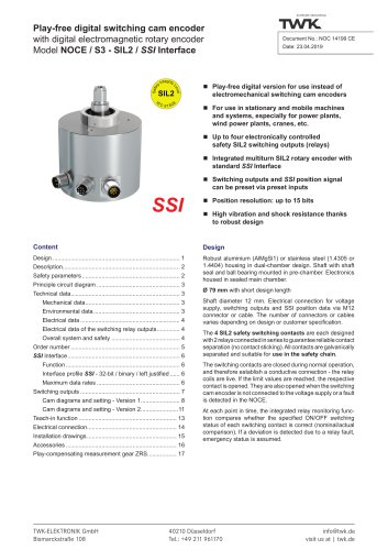
Inductive Linear Displacement Transducers Model IW 260 Measuring strokes: 80 mm, 170 mm, 240 mm, 360 mm Contactless, robust sensor system Infinite resolution, no hysteresis Calibrated output signals: 0...20 mA, 4...20 mA, ± 10 V, 0...10 V Integral electronics for DC in / DC out Accuracy up to 0.1 % Definite repeatability Protection class IP 66 Construction and operating principle The displacement transducer operates according to the principle of fractional inductivity allotment within the hollow coil. Depending on the position of the core the inductivity changes within the corresponding coil section. This kind of layout provides for more position data than the classical half-bridge or LVDT configuration. An integral electronic circuit transforms these data into a signal proportional to the displacement of the plunger core. The electronic circuits contains an oscillator, demodulator, an amplifier and in some cases a current output source. Standard measuring strokes: 80 mm 170 mm 240 mm 360 mm TWK-ELEKTRONIK GmbH Heinrichstrasse 85 Its SMD-design is short-circuit proof and protected against reverse polarity. The sensor system is completely sealed within a non-corrosive steel case to ensure positive protection against vibration, shock, humidity, oil and corrosive matter. The new principle of fractional inductivity allotment as described above brings about an outstanding increase of the measuring stroke. In comparison to the IW 250 model the useful range of the IW 260 model increases by 70 to 100% based on the same length of the case. Special calibration using the standard case lengths can be provided upon request, e.g. measuring stroke 150 mm equals 20 mA at case L2 = 250 mm.
カタログの1ページ目を開く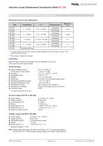
Standard versions and calibrations Type Increasing means that the output signal increases positively when the plunger is moved in the direction towards the plug. Other supply voltages upon request. Calibration Both the sensor system and plunger core They carry the same serial number. Technical data ■ Supply voltage range VS: (prot'd against reverse polarity) ■ Accuracy: ■ Temperature drift: ■ Stability: ■ Dalay time: ■ Operating temperature range: ■ Storage temperature range: ■ Resistance to shock: ■ Resistance to vibration: ■ Protection class: * For special calibration 0.5 % only. 21.5 to...
カタログの2ページ目を開く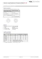
Electrical connections (with view on the contacts at the transducer case.) Materials Chrome-nickel steel Chrome-nickel steel Mu-metal Brass, nickel-plated Gold-plated □ External and internal tube: □ Plunger: □ Core: □ Connector case: □ Connector contacts: Lengths and masses (refer to drawings page 5) L1 = Plunger in central position: Io = 10 (12) mA, resp. Vo = 0 (5) V. Date: 02.02.2016 Page 3 of 6 Document no. IW 10505 JE
カタログの3ページ目を開く
Electrical and mechanical variants * 01 Standard Ball joint on case (back): KHN Ball joint on case Ball joint (in front): KV Ball joint on plunger, without guide KFN Ball joint on plunger, with guide Accuracy: 0.1 % 0.25 % 0.5 % Measuring stroke: 80 mm 170 mm 240 mm 360 mm 261 Current or voltage output and sense (see page 1) 262 263 264 265 IW Inductive linear displacement transducer The applicable A-No. is allocated after the definition of the deviation when ordering. No A-No. is given for standard versions as specified in the data sheet. Special Versions and accesories SR: Protective tube...
カタログの4ページ目を開く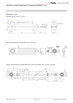
Inductive Linear Displacement Transducers Model IW 260 Installation drawings Dimensions in mm Stainless steel tube 1,4301 Standard version (without rod guide) Version with ball joint on plunger (KV) (without rod guide) pivot angle 13˚ Ball joint head to DIN 648 Version with ball joints on plunger (KFN) and on end of case (KFH) (with rod guide, captivated) Brass guide sleeve
カタログの5ページ目を開く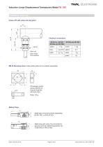
Version PK with cable exit and gland Electrical connections MB 25 Mounting block, brass Nickel plated (to be ordered separately) 22 hexagon socket screws M4/35 mm long are supplied with each item. Mass: 60 g Mating Plugs Metal case (must be ordered separately) BI 681 3PS or 4PS (IP 40) Metal case with outer ring connected to ground (must be ordered separately). BI 723M 3PS or 4PS (IP 66) Date: 02.02.2016 Page 6 of 6 Document no. IW 10505 JE
カタログの6ページ目を開くTWK-ELEKTRONIK GmbHのすべてのカタログと技術パンフレット
-
 Rotary encoder TBN58/C3
22 ページ
-
 Rotary encoder TBD
12 ページ
-
 Rotary encoder TBE58
16 ページ
-
 Rotary encoder KRP
7 ページ
-
 Rotary encoder TBN50/C3
22 ページ
-
 Product range 2022
64 ページ
-
 Image brochure TWK
28 ページ
-
 Inclinometer NBA51
6 ページ
-
 Rotary encoder TBA42
16 ページ
-
 Rotary encoder TRA42
16 ページ
-
 Rotary encoder TRN58/C3
22 ページ
-
 Manual TRN50/C3
86 ページ
-
 Rotary encoder TRN50/C3
22 ページ
-
 Rotary encoder TRN42/C3
22 ページ
-
 Rotary encoder TBN42/C3
22 ページ
-
 Rotary encoder TRE58
16 ページ
-
 Rotary encoder TRT
14 ページ
-
 Vibration sensor NVA
12 ページ
-
 Inclinometer NBN
17 ページ
-
 Inclination sensor NBT
10 ページ
-
 Inclinometer NBA
17 ページ
-
 Inclinometer NBN/S3 SIL2
13 ページ
-
 Rotary encoder TBE50
16 ページ
-
 Rotary encoder HBE
14 ページ
-
 Rotary encoder TRK
11 ページ
-
 Rotary encoder TMN50
6 ページ
-
 Rotary encoder TRE42
6 ページ
-
 Rotary encoder TRE50
6 ページ
-
 Rotary encoder TRA50
6 ページ
-
 Rotary encoder TBE42
6 ページ
-
 Rotary encoder TME42
6 ページ
-
 Rotary encoder TRD
12 ページ
-
 Rotary encoder TME50
6 ページ
-
 Rotary encoder TBN36
6 ページ
-
 Rotary encoder TMA50
6 ページ
-
 Rotary encoder TMN42
6 ページ
-
 Rotary encoder TMA42
6 ページ
-
 Rotary encoder TBA50
16 ページ
-
 Rotary encoder TBE36
6 ページ
-
 Rotary encoder TBN42
6 ページ
-
 Rotary encoder TBN37
8 ページ
-
 Rotary encoder TBA37
7 ページ
-
 Rotary encoder TBB50
16 ページ
-
 Rotary encoder PBA12
2 ページ
-
 Rotary encoder TBA36
6 ページ
-
 Rotary encoder TKA60
2 ページ
-
 Rotary encoder TKN46
7 ページ