カタログの抜粋

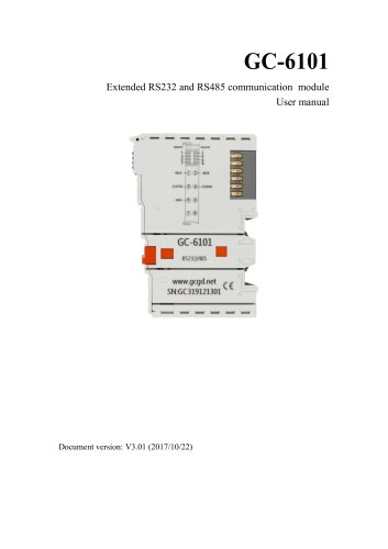
GC-6501 Extended Wifi communication module User manual
カタログの1ページ目を開く
Vhandy Technology Revise history Reason Create document Correct equipment working parameters Adjust the document structure
カタログの2ページ目を開く
Vhandy Technology
カタログの3ページ目を開く
Vhandy Technology 1. Function introduction 1.1 Functional Overview The GC-6501 module is an extended communication module that integrates 1 channel Wifi. This module can be used to expand Wifi communication, and can be connected to AP nodes, collect data through TCP and UDP communication, and send the collected values to the GCAN-PLC-510 series PLC controller through the internal bus, and at the same time expand the serial port function by calling Block programming to achieve complex bus control requirements. This module can be used in conjunction with any other GC series IO module to...
カタログの4ページ目を開く
Vhandy Technology 2. Equipment installation and use This chapter will explain in detail the installation method, wiring method, meaning of indicator lights and interface meaning of GC-6501 module. 2.1 Module fixed The installation method of GC-6501 module is shown in Figure 2.1, you need to use a flat-blade screwdriver to assist installation. Figure 2.1 GC-6501 Module installation First, you need to install the fieldbus coupler on the rail, and then attach the GC-6501 module to the right side of the fieldbus coupler or other modules to add this component. Please insert the GC-6501 module...
カタログの5ページ目を開く
Vhandy Technology Figure 2.2 GC-6501 module installation Figure 2.3 GC-6501 module wiring terminal block The wiring terminal block of the GC-6501 module is shown in Figure 2.3. GC6501 includes 1 Wifi extension function. The serial number corresponding to each terminal and its meaning are shown in Table 2.1.
カタログの6ページ目を開く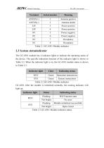
Vhandy Technology Serial number ANTEN(+) 1 Antenna positive ANTEN(-) 2 Antenna shield 24V 3 Power positive 24V 4 Power positive 0V 5 Power negative 0V 6 Power negative NC 7 Occupancy NC 8 Occupancy Table 2.1 GC-6501 Module indicator 2.3 System statusindicator The GC-6501 module has 4 indicator lights to indicate the operating status of the device. The specific indication function of the indicator light is shown in Table 2.2. When the indicator light is on, the GC-6501 module status is shown in Table 2.3. Indicator light Indicating status RUN Green Operation instructions SYS Green System...
カタログの7ページ目を開く
Vhandy Technology 2.4 Instructions GC-6501 module can directly refer to the routines shipped with PLC, the specific routines are as follows. VAR inst0_EXT_WIFI_INIT:EXT_WIFI_INIT; mEn:bool; mError:usint; wifiInit:bool:=false; rec:string(250); reclen:int; inst2_EXT_WIFI_READ_STR:EXT_WIFI_READ_STR; inst4_EXT_WIFI_WRITE_STR:EXT_WIFI_WRITE_STR; inst6_EXT_WIFI_READ_BIN:EXT_WIFI_READ_BIN; inst7_EXT_WIFI_WRITE_BIN:EXT_WIFI_WRITE_BIN; recd :array[0..200] of byte; pt_rec:pointer; END_VAR; if wifiInit=falsethen inst0_EXT_WIFI_INIT(EN_IN :=1 , NUMBER :=1 , MODE :='TCP' ,// Two working modes of TCP and...
カタログの8ページ目を開く
Vhandy Technology wifiInit:=true; end_if; else pt_rec:=&recd; inst6_EXT_WIFI_READ_BIN(EN_IN :=1 , NUMBER := 1, PTR_RXDATA :=pt_rec ,MAXLENGTH:=200 | mEn:=EN_OUT, reclen:= RXLENGTH, mError:=ERROR); if reclen>0 then inst7_EXT_WIFI_WRITE_BIN(EN_IN :=1 , NUMBER :=1 , PTR_TXDATA := pt_rec,TXLENGTH:=reclen | mEn:= EN_OUT, mError:=ERROR); else inst7_EXT_WIFI_WRITE_BIN(EN_IN :=0 , NUMBER :=1 , PTR_TXDATA := pt_rec, TXLENGTH :=reclen| mEn := EN_OUT, mError:=ERROR); end_if; end_if;
カタログの9ページ目を開く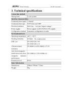
Vhandy Technology 3. Technical specifications Connection method Wiring form 2-wire system Interface characteristics Communication signal 1 channel Communication type TCP Client and UDP Electrical isolation 500 Vrms (GC-bus/ Signal voltage) Power supply Power supply via GCAN-PLC-510 coupler Configuration method Automatic configuration in order Environmental test Operating temperature -40℃~+85℃ Working humidity Vibration/shock resistance Anti-electromagnetic interference/anti-electr omagnetic radiation performance Protection level Basic Information Dimensions Weight
カタログの10ページ目を開く
Vhandy Technology 4. Disclaimer Thank you for purchasing GCAN's GCAN series of hardware and software products. GCAN is a registered trademark of Shenyang Vhandy Technology Co., Ltd. This product and manual are copyrighted by Vhandy Technology. Without permission, it is not allowed to reproduce in any form. Before using, please read this statement carefully. Once used, it is deemed to be an endorsement and acceptance of the entire content of this statement. Please strictly abide by the manual, product description and related laws, regulations, policies and guidelines to install and use the...
カタログの11ページ目を開く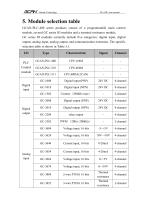
Vhandy Technology 5. Module selection table GCAN-PLC-400 series products consist of a programmable main control module, several GC series IO modules and a terminal resistance module. GC series IO modules currently include five categories: digital input, digital output, analog input, analog output, and communication extension. The specific selection table is shown in Table 5.1. I/O relay output Voltage input, 16 bits Voltage input, 16 bits Digital input Current input, 16 bits Current input, 16 bits Voltage input, 16 bits Voltage input, 16 bits Thermal resistance Thermal resistance
カタログの12ページ目を開く
Vhandy Technology Voltage output, 16 bits Current output, 16 bits Current output, 16 bits Voltage output, 16 bits Voltage output, 16 bits Voltage output, 12 bits Special module Voltage output, 16 bits Analog output K type / S type / T type thermocouple GPRS extension WiFi extension Table 5.1 Selection table
カタログの13ページ目を開く
Vhandy Technology Sales and service Shenyang Vhandy Technology Co., Ltd. Address: Room 401, D11 Block, SISP., Hunnan District, Shenyang, Liaoning, China E-mail: info@gcanbus.com Tel/ Whatsapp: +86-13644001762 Website: gcanbus.com
カタログの14ページ目を開くShenyang Vhandy Technology Co.のすべてのカタログと技術パンフレット
-
 GC-2018-8DO(NPN)
13 ページ
-
 GC-2008-8DO(PNP)
13 ページ
-
 GC-1018-8DI(NPN)
13 ページ
-
 GC-1008-8DI(PNP)
13 ページ
-
 GCAN-IO-8100
20 ページ
-
 GCAN-IO-8000
25 ページ
-
 GCAN-PLC-511
31 ページ
-
 GCAN-PLC-510
31 ページ
-
 GCAN-PLC-400
31 ページ