カタログの抜粋

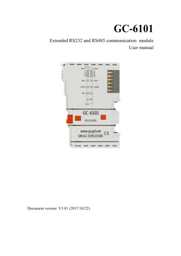
GC-1018 8-channel digital input module (NPN) User manual
カタログの1ページ目を開く
Vhandy technology Revision History Modify device parameters Modify device appearance picture
カタログの2ページ目を開く
Vhandy technology
カタログの3ページ目を開く
Vhandy technology 1. Introduction 1.1 Overview The GC-1018 module has integrated 8 digital input channels, which acquires digital signals in real-time and transmits them to the GCAN-PLC coupler. This module can be used with any other GC Series IO module to capture and process digital data in industrial automation or distributed control systems. 1.2 Properties at a glance ● 8 input channels ● Nominal voltage: 24V DC(±20%) ● Signal voltage "1":-3~+5V ● Signal voltage "0":11~30V ● Maximum input current:3mA ● Electrical isolation: 500 V(GC-bus) ● Current consumption:100mA ● The bit width input...
カタログの4ページ目を開く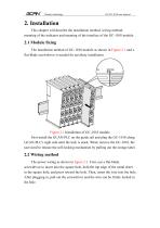
Vhandy technology 2. Installation This chapter will describe the installation method, wiring method, meaning of the indicator and meaning of the interface of the GC-1018 module. 2.1 Module fixing The installation method of GC-1018 module as shown in Figure 2.1 and a flat-blade screwdriver is needed for auxiliary installation. Figure 2.1 Installation of GC-1018 module First install the GCAN-PLC on the guide rail and plug the GC-1018 along GCAN-PLC's right side until the lock is stuck. When remove the GC-1018, the user need to release the self-locking mechanism by pulling out the orange...
カタログの5ページ目を開く
Vhandy technology Figure 2.2 Wiring method of GC-1018 module Figure 2.3 GC-1018 module terminal definition
カタログの6ページ目を開く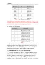
Vhandy technology Digital input 1 Digital input 2 Digital input 3 Digital input 4 Digital input 5 Digital input 6 Digital input 7 Digital input 8 Table 2.1 GC-1018 module indicator When using, please connect digital input signal to the terminal of GC-1018 and connect the reference ground to the negative power supply of GCAN-PLC-400 or GCAN-IO-8000 modules (corresponding to pins 5 and 6). 2.3 System statusindicator Indicators Digital input1 is valid. Digital input 2 is valid. Digital input 3 is valid. Digital input 4 is valid. Digital input 5 is valid. Digital input 6 is valid. Digital input...
カタログの7ページ目を開く
Vhandy technology In the process of ST programming definition, gc-1018 module needs to define variable type, input signal position, start character, delimiter and so on. For example: "DI0 AT%I0.0:BOOL;" "0.0" represents the position of the input point, and"0.0"~"0.7"respectively define the 1-8 input points in the first GC1018 module. When the user uses more thanone gc-1018 module, the second gc-1018 shall be defined from "1.0" to "1.7", and so on. "%" (percent sign) is the direct variable starter; ":" (colon) is the variable or type separator. The Boolean is read from the %I0.0 address...
カタログの8ページ目を開く
Vhandy technology 3. Technical Specifications Interface characteristics Number of inputs Signal voltage "1" Signal voltage "0" Input current (Max.) Electrical isolation Bit width in the process image Installation position Power supply Environmental testing Operating temperature Permissible relative humidity EMC test Vibration/shock resistance EMC resistance burst/ ESD Protection class Basic information Dimensions Weight 8 -3~+5V 11~30V 3mA 500 V(GC-bus/ Signal voltage) Input 1 byte In sequential order Powered by GCAN-PLC, current consumption 100mA -40℃~+85℃ 95%RH,no condensation EN...
カタログの9ページ目を開く
Vhandy technology 4. Disclaimer Thank you for purchasing GCAN's GCAN series of hardware and software products. GCAN is a registered trademark of Shenyang Vhandy Technology Co., Ltd. This product and manual are copyrighted by Vhandy Technology. Without permission, it is not allowed to reproduce in any form. Before using, please read this statement carefully. Once used, it is deemed to be an endorsement and acceptance of the entire content of this statement. Please strictly abide by the manual, product description and related laws, regulations, policies and guidelines to install and use the...
カタログの10ページ目を開く
Vhandy technology 5. Module selection table GCAN-PLC-400 series products consist of a programmable main control module, several GC series IO modules and a terminal resistance module. GC series IO modules currently include five categories: digital input, digital output, analog input, analog output, and communication extension. The specific selection table is shown in Table 5.1. I/O relay output Voltage input, 16 bits Voltage input, 16 bits Digital input Current input, 16 bits Current input, 16 bits Voltage input, 16 bits Voltage input, 16 bits Thermal resistance Thermal resistance
カタログの11ページ目を開く
Vhandy technology Voltage output, 16 bits Voltage output, 16 bits Current output, 16 bits Current output, 16 bits Voltage output, 16 bits Voltage output, 16 bits Voltage output, 12 bits Special module Analog output K type / S type / T type thermocouple GPRS extension WiFi extension Table 5.1 Selection table
カタログの12ページ目を開く
Vhandy technology Sales and service Shenyang Vhandy Technology Co., Ltd. Address: Room 401, D11 Block, SISP., Hunnan District, Shenyang, Liaoning, China E-mail: info@gcanbus.com Tel/ Whatsapp: +86-13644001762 Website: gcanbus.com
カタログの13ページ目を開くShenyang Vhandy Technology Co.のすべてのカタログと技術パンフレット
-
 GC-2018-8DO(NPN)
13 ページ
-
 GC-2008-8DO(PNP)
13 ページ
-
 GC-1008-8DI(PNP)
13 ページ
-
 GCAN-IO-8100
20 ページ
-
 GCAN-IO-8000
25 ページ
-
 GCAN-PLC-511
31 ページ
-
 GCAN-PLC-510
31 ページ
-
 GCAN-PLC-400
31 ページ