RIGCHINA-Differential sticking tester | RCD-12 | determine how likely a given drilling fluid will be to produce a "stuck pipe" situation and how effective a given drilling fluid treatment
1 /
23ページ

カタログの抜粋

Differential sticking tester Instruction Manual RIGCHINA's products meet all the requirements of the API standard procedures for testing wwater base Drilling fluids,Oil base drilling fluids and oil well cements Contact Rigchina Group Company for more information on our completer line of Drilling Fluids Testing Equipments Call us today, or v i sist our website at www.rigchina.com 1
カタログの1ページ目を開く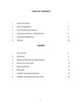
General Information Safety Considerations Timed Filtration Test Procedure Calculations and Theory of Measurements Parts List Cell Assembly Cell Section Closing and Opening Cell (Opening shown) Sticking The Torque Plate Measuring Sticking Work Sheet Exploded View Pressure Regulator Exploded View Differential Sticking Tester
カタログの2ページ目を開く
SECTION 1 GENERAL INFORMATION The Differential Sticking Tester Apparatus was designed to determine how likely a given drilling fluid will be to produce a "stuck pipe" situation and how effective a given drilling fluid treatment or application of spotting fluid in any given drilling fluid would be in reducing this tendency. This measurement is called the "Stuck Tendency Coefficient". It takes into account both the stickiness and the cake building capability of the drilling fluid. The "Stuck Tendency Coefficient" is determined by the Timed Filtrate Test. The unit can be pressurized by the CO2...
カタログの3ページ目を開く
SECTION 2 SAFETY CONSIDERATIONS Safe operation of the Differential Sticking Tester requires that the operator understand and practice the correct assembly and operation of the equipment. Improper assembly, operation, or the use of defective parts poses the possibility of cell leakage or failure which could result in serious injury and damage. Following is a list of suggestions that should be observed to assure safe operation and maintenance of the Differential Sticking Tester. A. Safe Pressurization 1. Always use either Carbon Dioxide or Nitrogen. Never connect the Differential Sticking...
カタログの4ページ目を開く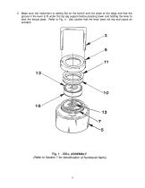
2. Make sure the instrument is setting flat on the bench and not close to the edge and that the groove in the lever is fit under the top leg support before pressing down and holding the lever to stick the torque plate. Refer to Fig. 4. Use caution that the lever does not slip and cause an accident.
カタログの5ページ目を開く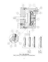
(Refer to Section 7 for identification of Numbered items)
カタログの6ページ目を開く
SECTION 3 TIMED FILTRATION STICKING TEST PROCEDURE (Numbers in [ ] refer to Fig. 1 thru 5) The general procedure for assembling and operating the instrument is basically the same whether the test described in Section 3 or Section 4 is being run. Ensure that the apparatus is clean. Refer to Section 6. The timed filtration sticking test uses a predetermined sticking time to determine the sticking coefficient. In this test the stuck tendency coefficient Kst is determined. If the flat plate [9] is used R = 1 with edge effects considered. Refer to Step B-3 below. If the radius'd plate [15] is...
カタログの7ページ目を開く
12. Close the bleed valve on the CO2 assembly. 13. Turn the regulator handle counterclockwise until the diaphragm pressure is relieved. 14. Insert the CO2 cartridge [25] into the knurled CO2 holder. Tighten the holder onto the head, puncturing the cartridge. 15. Place graduated cylinder [29] under the cell and turn the lower valve stem valve 1/4 turn counterclockwise from hand-tight. 16. Adjust the regulator to 477.5 PSI (3292 kPa). B. Running The Sticking Test 1. Verify the torque plate stem is up as far as possible by turning and pulling upward at the same time. 2. Open the top valve-stem...
カタログの8ページ目を開く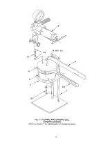
Fig. 3 - CLOSING AND OPENING CELL (OPENING SHOWN) (Refer to Section 7 for Identification of Numbered items)
カタログの9ページ目を開く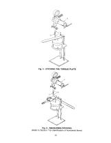
Fig. 4 - STICKING THE TORQUE PLATE (Refer to Section 7 for Identification of Numbered items)
カタログの10ページ目を開く
10. Record each of these readings, then calculate the average torque reading. Record the plate sticking time. 11. Turn the regulator handle counterclockwise until the diaphragm pressure is not felt. Then open the bleed-off valve. C. Dis-assembly and Cleaning 1. Remove the empty CO2 cartridge (if spent.) 2. Remove the torque wrench and socket. 3. Pull pin [26] and remove the CO2 assembly [2]. 4. Remove the top valve stem [17]. 5. Loosen the cell cap [6], then unscrew and remove it. If the torque plate remains stationary while loosening and unscrewing the cell cap, carefully push it through...
カタログの11ページ目を開く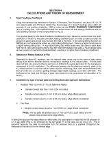
SECTION 4 CALCULATIONS AND THEORY OF MEASUREMENT A. Stuck Tendency Coefficient Using the standard test described in Section 3 "Standard Test Procedure" and the 12.5" (31.75 cm) radius'd plate and 477.5 psi (3292 kPa), the average of 6 "break" readings taken within 30 seconds of one another divided by 1000 is known as the STUCK TENDENCY COEFFICIENT (Kst) of a drilling fluid. This coefficient takes into account both the bulk sticking coefficient and the cake-building character of the sample (Refer to Fig. 2). The physical basis for the Stuck Tendency Coefficient is that it takes into account...
カタログの12ページ目を開く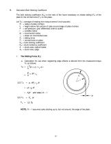
Derivation-Bulk Sticking Coefficient The bulk sticking coefficient (Ksc) is the ratio of the force necessary to initiate sliding (Fs) of the plate to the normal force (Fn) on the plate. Let Tu = average of reading from torque wrench (inch-pounds) R = radius of plate (inches) h = height above flat surface of cake around edge of plate (inches) P = cell pressure, (psi) differential (inlet to outlet) r = variable radius dr = incremental radius τy = shear on incremental area Fs = sliding force Fn = normal force on plate Ksc = bulk sticking coefficient Kst = stuck tendency coefficient A = stuck...
カタログの13ページ目を開く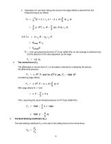
b. Calculation for use when taking into account the edge effects is derived from the measured torque as follows: R = 1 inch and assuming that the 477.5 psi (3292 kPa) on the average is achieved only 2/3 the distance of the cake deposition up the edge: The normal force (Fn) The differential or normal force (Fn) on the plate is derived by multiplying the area by the differential pressure: Considering edge effects: With edge effects R = 1 inch Then, assuming the recommended pressure of 477.5 psi (3292 kPa) The Bulk Sticking Coefficient (Ksc) The bulk sticking coefficient Ksc is the ratio of...
カタログの14ページ目を開くRIGCHINA GROUP COMPANYのすべてのカタログと技術パンフレット
-
 12 Speed Viscometer
23 ページ
-
 6 Speed Viscometer
23 ページ
-
 Garrett Gas Train
28 ページ
-
 Core Saturator
4 ページ
-
 Deadline Anchors
11 ページ
-
 Weight Indicator systems
11 ページ
-
 MUD PUMP PRESSURE GAUGES
19 ページ
-
 DRILLING INSTRUMENTATION
38 ページ
-
 Oil and Water Retort Kit
19 ページ