
カタログの抜粋
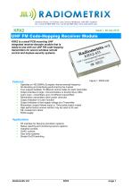
KRX2 is a small PCB mounting UHF integrated receiver-decoder module that is ready-to-use with our UHF FM code-hopping transmitters for secure wireless remote control and keyless security systems. ■ Operates on 433.92MHz European licence exempt frequency ■ All decoding and interfacing performed by the module ■ Four outputs facilitate 15 different control codes for each transmitter ■ Output interface to logic, microcontrollers or directly drive LEDs ■ Learn input - remembers up to 16 different transmitters ■ Remembers transmitters when power removed ■ Output indication of Learn function ■ Output indication of low supply voltage at a Transmitter ■ Momentary (output follows input) or 10ms pulse output modes ■ High performance receiver section may be used on its own ■ DIL module form factor ■ 5VDC supply Applications ■ RF interface for Security and Alarm systems ■ Status reporting and monitoring secure systems ■ Industrial controls ■ HVAC controls ■ Door entry systems ■ Simple On/Off switching
カタログの1ページ目を開く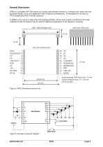
General Description KRX2 is a complete UHF FM receiver and rolling code decoder/interface in a compact form factor that may be placed directly into an end application with no special considerations. It is designed for use with our KTX2 module and KFX2 “Key-fob” products. In addition to its use as a ready-built code-hopping decoder, all the usual receiver connections are made available so that the receiver may be used for additional applications of the designer’s choosing. side view (through can) side view (with can) 6 mm 6 mm top view (without can) 1 RSSI RESERVED 2 0V 3 4 0V LRN (OUT) 5 6...
カタログの2ページ目を開く
Using KRX2 A simple connection diagram for experimental purposes is shown in Figure 3. The Mode switch is connected between MODE and 0V and the Learn button is connected between LRN (IN) and 0V. The antenna can be just a few centimetres of wire, for test purposes. Refer to antenna requirements at the end of this datasheet for operational recommendations. The 5V shown would normally be supplied by a regulated low-noise PSU. Remaining digital outputs are all connected to LEDs to show the operation of the module. CAUTION! Take care that the supply never exceeds 5.5 V, even momentarily: if this...
カタログの3ページ目を開く
Activating outputs Once a transmitter has been learned its transmissions will be acted upon, i.e. the function code contained within the transmission is fed to the KRX2 outputs S0 – S3. Either a 10ms single-shot output or a longer momentary output can be used according to the MODE selected. In the circuit shown in Fig. 3, closing the switch will select “momentary” mode. In 10ms “single-shot” mode the ouput(s) are activated for only 10ms (nominal) per message received. This means that regardless of whether someone “holds down the button” at the sending device, the KRX2 output will only be a...
カタログの4ページ目を開く
Figure 4: Timing diagram – showing action upon receiving a message with S0 = 1 Received Signal Strength Indication (RSSI) The KRX2 module incorporates a wide range RSSI that measures the strength of an incoming signal over a range of approximately 60dB. This allows assessment of link quality and available margin and is useful when performing range tests. Please note that the actual RSSI voltage at any given RF input level varies somewhat between units. The RSSI facility is intended as a relative indicator only - it is not designed to be, or suitable as, an accurate and repeatable measure of...
カタログの5ページ目を開く
Absolute maximum ratings Survival Maximums: Exceeding the values given below may cause permanent damage to the module. Operating temperature -Storage temperature DC supply (pin 8) RSSI, AF, RXD (pins 1,7,6) RF IN (pin 1) Digital inputs/outputs (DC supply = 5.0V / temperature = 20 °C unless stated) min. typ. max. units notes DC supply Supply voltage Supply current RF/ IF RF centre frequency RF sensitivity for 12dB (S+S/N) RSSI range IF bandwidth Image rejection IF rejection (10.7MHz) LO leakage, conducted Baseband AF level DC offset on AF out Distortion on recovered AF Load capacitance,...
カタログの6ページ目を開く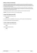
Module mounting considerations Good RF layout practice should be observed – in particular, any ground return required by the antenna or feed should be connected directly to the RF GND pin at the antenna end of the module, and not to the OV pin which is intended as a DC ground only. All connecting tracks should be kept as short as possible to avoid any problems with stray RF pickup. If the connection between module and antenna does not form part of the antenna itself, it should be made using 50Ω microstrip line or coax or a combination of both. It is desirable (but not essential) to fill all...
カタログの7ページ目を開く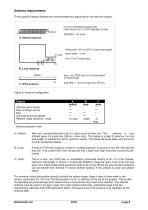
Three types of integral antenna are recommended and approved for use with the module: 0.5 mm enameled copper wire close wound on 3.2 mm diameter former 433 MHz = 24 turns Feed point 15% to 25% of total loop length track width = 1mm 4 to 10 cm inside area o RF C. Whip antenna wire, rod, PCB-track or a combination of these three 433 MHz = 16.4 cm total from RF pin. Figure 6: Antenna configuration Feature ABC helical loop whip Ultimate performance ** * *** Easy of design set-up ** * *** Size *** ** * Immunity proximity effects ** *** * Relative range...
カタログの8ページ目を開く
Copyright notice This product data sheet is the original work and copyrighted property of Radiometrix Ltd. Reproduction in whole or in part must give clear acknowledgement to the copyright owner. Limitation of liability The information furnished by Radiometrix Ltd is believed to be accurate and reliable. Radiometrix Ltd reserves the right to make changes or improvements in the design, specification or manufacture of its subassembly products without notice. Radiometrix Ltd does not assume any liability arising from the application or use of any product or circuit described herein, nor for...
カタログの9ページ目を開くRadiometrixのすべてのカタログと技術パンフレット
-
 LNM2H
LNM2H13 ページ
-
 NiM1B
NiM1B13 ページ
-
 VX2M
VX2M9 ページ
-
 WRX2C
WRX2C9 ページ
-
 MSR3
MSR38 ページ
-
 LMR0
LMR010 ページ
-
 SAT3
SAT35 ページ
-
 NTX2B
NTX2B13 ページ
-
 NTX0
NTX08 ページ
-
 MTX3
MTX310 ページ
-
 MTX2
MTX210 ページ
-
 BiM3H
BiM3H8 ページ
-
 QPX1
QPX18 ページ
-
 QPT1
QPT18 ページ
-
 AiM1
AiM19 ページ
-
 Universal Evaluation Kit
27 ページ
-
 TDL2A Evaluation Kit
4 ページ
-
 SP2 Evaluation Kit
12 ページ
-
 M48A Application Board
12 ページ
-
 M1144
M11448 ページ
-
 DXT / DXR
7 ページ
-
 CTA28 App. boards
11 ページ
-
 BL118
BL1187 ページ
-
 BD118
BD1185 ページ
-
 PAN1311
2 ページ
-
 PAN1310
2 ページ
-
 m48a
m48a11 ページ
-
 LMR2
LMR211 ページ
-
 TDL3F
TDL3F10 ページ
-
 KTX2
KTX28 ページ
-
 RPM3
RPM315 ページ
-
 ENX1
ENX111 ページ
-
 NiM2
NiM211 ページ
-
 BiM1
BiM115 ページ
-
 RX3G
RX3G6 ページ
-
 PLR2
PLR212 ページ
-
 MSR3
MSR38 ページ
-
 CXR2
CXR212 ページ
-
 COR3
COR38 ページ
-
 TX2S
TX2S7 ページ
-
 CXT2
CXT212 ページ
-
 KRX2
KRX29 ページ
-
 KFX2
KFX24 ページ
-
 KDEC
KDEC5 ページ
-
 TXL2
TXL211 ページ
-
 Radiometrix
20 ページ


