
カタログの抜粋

The CTA88 chip is a simple encoder/decoder for use with ISM band telemetry modules. It permits a simple, one way wireless link to be established, for simple remote control applications, with a minimum of effort and no customer software input. These tx and rx application boards are designed to allow easy evaluation of the CTA88 device in elementary jobs. They provide a simple 2 channel implementations, using either LMT/LMR or BiM footprint radio modules ■ 8 bit address and 2 bit data select switches ■ 2 relays to control mains powered devices rated up to 8A, 250VAC/30VDC ■ Visual indication of valid code received and active relays ■ RF module range testing ■ Push button for momentary control of relays ■ Momentary, Latched outputs ■ Dynamic relay state changes ■ Setup is simple as Plug-and-Play ■ RF Remote Control Demonstration Kit Contents The CTA28 Application kit is supplied with the following contents: 2 CTA88-000-DIL 1 Radiometrix T ransmitter module (ordered separately) 1 Radiometrix Receiver module (ordered separately) 2 1/4-wavelength monopole or helical antennas (ordered separately) 2 Jumpers 1 CTA88 data sheet 1 CTA28 Application board manual 1 Data sheet of Radio module ordered ■ External power supply or 12V DC power adaptor Radiometrix Ltd CTA28 Demo board page 1
カタログの1ページ目を開く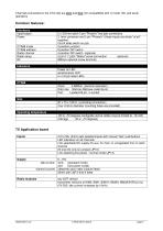
Channels connected on the CTA chip are zero and four (for compatibility with rx mode 100, and serial operation) Common features: Radiometrix Ltd CTA28 Demo board page 2
カタログの2ページ目を開く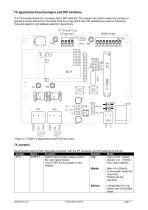
The TX encoder board has 4 jumpers and 2 DIP switches. The jumpers are used to select the number of operating modes featured in the board while the 4 way and 8 way DIP switches are used for frequency channels selection and address selection respectively. Contact Contact Input Input Figure 2: CTA28 TX application board PCB (top view) Assumed the board is held "long side horizontal" with the RF connector and DIP switches at the top Jumper. Name Function Position Selects which power supply is fed to the user inputs busbar (Only EVER fit one jumper on this header) Low current / always...
カタログの3ページ目を開く
TX DIP switches The TX encoder board has 4 jumpers and 2 DIPswitches. The jumpers are used to select the number of operating modes featured in the board while the 4 way and 8 way DIP switches are used for frequency channels selection and address selection respectively. Radiometrix Ltd CTA28 Demo board page 4
カタログの4ページ目を開く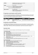
Radiometrix Ltd CTA28 Demo board page 5
カタログの5ページ目を開く
Which modes to use? The CTA88 have a variety of operating modes. These are better understood by relating them to different applications: 1. Wire replacment:. Operate transmitter in mode 010 (continuous: allows the STB output to be used as a 'good link' indicator) and receiver in mode 001. If receiver operates in latched (011) mode then 'chattering' of the output is reduced (at extreme range, or with interferers present), but the link is no longer fail safe Latched mode is also compatible with send on change (011) 2. Momentary push buttons: Transmitter in mode 100 (send while any input is...
カタログの6ページ目を開く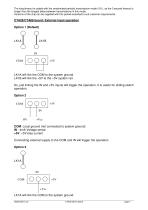
The long timeout is usable with the randomised periodic transmission mode (101), as the 3 second timeout is longer than the longest delay between transmissions in this mode. Versions of the chip can be supplied with this period extended to suit customer requirements CTA28/CTA88 board: External input operation LK1A will link the COM to the system ground. Radiometrix Ltd CTA28 Demo board page 7
カタログの7ページ目を開く
Figure 4: CTA28 Encoder Transmitter Schematics
カタログの8ページ目を開く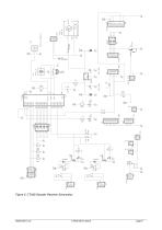
Figure 5: CTA28 Decoder Receiver Schematics
カタログの9ページ目を開く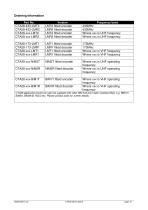
Ordering Information Radiometrix Ltd CTA28 Demo board page 10
カタログの10ページ目を開く
Copyright notice This product data sheet is the original work and copyrighted property of Radiometrix Ltd. Reproduction in whole or in part must give clear acknowledgement to the copyright owner. Limitation of liability The information furnished by Radiometrix Ltd is believed to be accurate and reliable. Radiometrix Ltd reserves the right to make changes or improvements in the design, specification or manufacture of its subassembly products without notice. Radiometrix Ltd does not assume any liability arising from the application or use of any product or circuit described herein, nor for...
カタログの11ページ目を開くRadiometrixのすべてのカタログと技術パンフレット
-
 LNM2H
LNM2H13 ページ
-
 NiM1B
NiM1B13 ページ
-
 VX2M
VX2M9 ページ
-
 WRX2C
WRX2C9 ページ
-
 MSR3
MSR38 ページ
-
 LMR0
LMR010 ページ
-
 SAT3
SAT35 ページ
-
 NTX2B
NTX2B13 ページ
-
 NTX0
NTX08 ページ
-
 MTX3
MTX310 ページ
-
 MTX2
MTX210 ページ
-
 BiM3H
BiM3H8 ページ
-
 QPX1
QPX18 ページ
-
 QPT1
QPT18 ページ
-
 AiM1
AiM19 ページ
-
 Universal Evaluation Kit
27 ページ
-
 TDL2A Evaluation Kit
4 ページ
-
 SP2 Evaluation Kit
12 ページ
-
 M48A Application Board
12 ページ
-
 M1144
M11448 ページ
-
 DXT / DXR
7 ページ
-
 BL118
BL1187 ページ
-
 BD118
BD1185 ページ
-
 PAN1311
2 ページ
-
 PAN1310
2 ページ
-
 m48a
m48a11 ページ
-
 LMR2
LMR211 ページ
-
 TDL3F
TDL3F10 ページ
-
 krx2
krx29 ページ
-
 KTX2
KTX28 ページ
-
 RPM3
RPM315 ページ
-
 ENX1
ENX111 ページ
-
 NiM2
NiM211 ページ
-
 BiM1
BiM115 ページ
-
 RX3G
RX3G6 ページ
-
 PLR2
PLR212 ページ
-
 MSR3
MSR38 ページ
-
 CXR2
CXR212 ページ
-
 COR3
COR38 ページ
-
 TX2S
TX2S7 ページ
-
 CXT2
CXT212 ページ
-
 KRX2
KRX29 ページ
-
 KFX2
KFX24 ページ
-
 KDEC
KDEC5 ページ
-
 TXL2
TXL211 ページ
-
 Radiometrix
20 ページ


