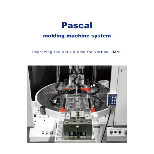
カタログの抜粋
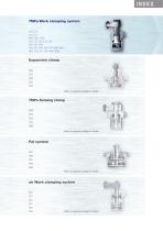
INDEX 7MPa Work clamping system CTU CTT CLU CLT CNA CMC CMD CSU CST CSN CSY CSK CEK CEA CVH VCB VCP VHD VRG VEF WPB WPC HCD HCS HCT X63 WRA WRB Expansion clamp CGC CGT CGU CGE CGY Refer to separate catalog for details. 7MPa Sensing clamp CTM CTN CLM CLN CNB Refer to separate catalog for details. Pal system CPC CPH CPY CPK WVP Refer to separate catalog for details. air Work clamping system CTX CTY CLX CLY CSS CSX Refer to separate catalog for details.
カタログの1ページ目を開く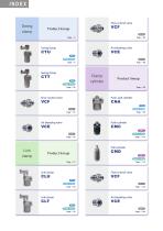
Swing clamp Flow control valve Product lineup Swing clamp Swing clamp Clamp cylinder Product lineup Flow control valve Push, pull cylinder Push cylinder Link clamp Pull cylinder Product lineup 35MPa Single acting Page → 118 Link clamp Flow control valve Link clamp
カタログの2ページ目を開く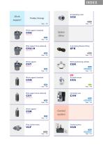
Work support Product lineup Work support Standard Option Other Hydraulic lift Work support Force enhanced G port piping flareless fitting Hydraulic lift Work support Work positioning cylinder Spring lift Work support Standard Hydraulic lift Work support Force enhanced Centering vise Hydraulic lift Work support Control system Spring lift Flow control valve Control system
カタログの3ページ目を開く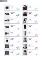
Pilot check valve Control unit Solenoid operated Double acting Page → 216 Control system 7MPa Double acting Page → 232 Control unit Solenoid operated Single acting Page → 218 Reducing valve 7MPa Single acting Page → 233 Control unit Manual operated Sequence valve Pascal pump Rotary joint Single rotary standard Rotary joint Single rotary with flange Control unit Rotary joint Manual operated Double rotary with flange Control unit Rotary joint Manual operated 7MPa Single acting Page → 231
カタログの4ページ目を開く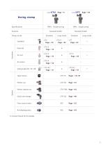
Swing clamp Long stroke CTU-S Page →22 Single acting Standard model Standard Long stroke Standard model Clamp stroke Double acting Taper sleeve Flow control valve
カタログの7ページ目を開く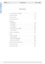
Swing clamp Swing clamp Structure, Hydraulic circuit diagram ……………………………………………… 6 Specifications, Piping ……………………………………………………………… 7 Performance table …………………………………………………………………… 8 Swing speed adjustment …………………………………………………………… 9 Dimensions Standard CTU …………………………………………………………………… 10 Dual rod CTU-E ………………………………………………………………… 14 Pin rod CTU-P …………………………………………………………………… 15 Air sensor CTU-A ………………………………………………………………… 16 Swing angle 30° , 45° , 60°CTU-N ……………………………………………… 21 Long stroke CTU-S ……………………
カタログの8ページ目を開く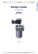
Swing clamp Double acting Swing clamp Swing clamp Double acting 7 MPa Standard model model To download CAD data / To get updated information, visit www.pascaleng.co.jp
カタログの9ページ目を開く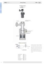
CTU□ - □□ Swing clamp Swing clamp Double acting Standard model Positioning pin groove for clamp arm Hydraulic pressure (G port piping) Hydraulic pressure (manifold piping) Hydraulic circuit diagram For flow control valve, we recommend the meter-in control. If meterout control is used, due to the area difference, it will cause back pressure and become high pressure. This can Flow control valve model VCF (option) lead to malfunction of the system. Please be aware when designing the circuit. Swing angle 30 , 45 , 60 page → 20 Long s
カタログの10ページ目を開く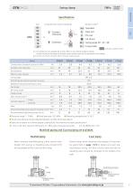
Double acting Swing clamp Swing clamp Specifications Swing direction (when clamping) indicates made to order. 1:All varieties are not available for all sizes. Refer to each relevant page for details. Contact Pascal for the details of variation codes (models) that are not described in the catalog. 2:CTU25-□E, CTU25-□P and CTU25-□S30 are made to order. Model Cylinder force (hydraulic pressure 7MPa) Cylinder inner diameter Effective area (clamp) Swing angle Positioning pin groove position accuracy Repeated clamp positioning accuracy Full stroke Clamp stroke Max. swing torque Cylinder capacity...
カタログの11ページ目を開く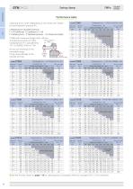
CTU□ - □□ Swing clamp Swing clamp Clamping force calculation formula F = P/(Coefficient 1 + Coefficient 2 × LH) F:Clamping force P:Hydraulic pressure CTU06 with clamp arm length (LH) = 60 mm Clamp arm length LH at hydraulic pressure of 7 MPa, (mm) Clamping force F is calculated by 7/(1.12+0.00422×60)=5.1 kN Cylinder force (kN) Do not use the clamp in the nonusable range. It may cause damage to the cylinder and rod. model CTU02 Hydraulic pressure MPa Clamping force Clamping force Max. arm length Max. LH Clamp arm length LH mm mm 60 80 100 120 140 160 180 Clamping force Clamping force Max....
カタログの12ページ目を開く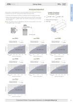
Double acting Swing clamp Swing clamp Swing speed adjustment Swing time is restricted by the mass and length of the clamp arm (moment of inertia) since the 90 swing action impacts the cam shaft. Example of calculation for moment of inertia 1. Calculate the moment of inertia according to the arm length and mass. 2. Adjust swing speed with flow control valve to ensure that 90 swing time of the clamp arm is greater than the shortest swing time in the graph shown below. I :Moment of inertia (kg·m2 ) m :Mass (kg) ● The cam groove may be damaged in case the swing speed is set at the nonusable...
カタログの13ページ目を開くPascal Engineering Inc.のすべてのカタログと技術パンフレット
-
 Pascal auto coupler
60 ページ
-
 Mold clamping system
136 ページ
-
 Press machine system
48 ページ
-
 Stamping die clamping system
254 ページ
-
 Pascal N2 gas springs
28 ページ
-
 mini Gas springs
40 ページ
-
 N2 gas springs
86 ページ
-
 Expansion clamp
142 ページ
-
 air Work clamping system
130 ページ
-
 35MPa Work clamping system
177 ページ
-
 Pal system
106 ページ
-
 Pascal mag clamp
72 ページ