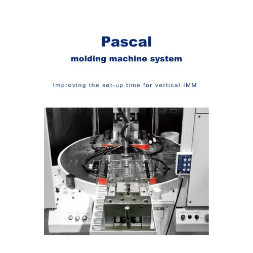
カタログの抜粋
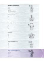
7MPa Work clamping system CTU CTT CLU CLT CNA CMC CMD CSU CST CSN CSY CSK CEK CEA CVH VCB VCP VHD VRG VEF WPB WPC HCD HCS HCT X63 WRA WRB Refer to separate catalog for details. Expansion clamp CGC CGT CGU CGE CGY Refer to separate catalog for details. 7MPa Sensing clamp CTM CTN CLM CLN CNB Refer to separate catalog for details. Pal system CPC CPH CPY CPK WVP Refer to separate catalog for details. air Work clamping system CTX CTY CLX CLY CSS CSX Refer to separate catalog for details. 35MPa Work clamping system CTK CTW CTV CLW CLV CSW CSV WVP VCB VCP VHD VRG VEF WPC HCD HCS HCT X63
カタログの1ページ目を開く
Link clamp Swing clamp Product lineup Compact model Swing clamp Link clamp Compact model Swing clamp Flow control valve Sensor model Flow control valve Work support Product lineup Swing clamp Work support Hydraulic lift Double acting Swing clamp Work support Hydraulic lift Single acting Page → 68 Link clamp 35MPa Double acting Page → 122 Work support Product lineup Spring lift
カタログの2ページ目を開く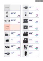
Sequence valve Non-leak coupler Non-leak coupler Control unit Manual operated Control unit Control system Manual operated 25MPa Single acting Page → 169 Coupling valve Control unit Solenoid operated Double acting Page → 156 Pilot check valve 25MPa Double acting Page → 170 Control unit Solenoid operated Double acting Page → 158 Coupling valve 25MPa Single acting Page → 171 Control unit Manual operated Single acting Page → 160 Reducing valve 25MPa Single acting Page → 172 Pascal pump
カタログの3ページ目を開く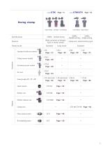
Swing clamp Upper flange Lower flange Double acting Wide varietions of designs Built-in sensor model Clamp stroke Standard (without sensor) r) Clamp sensor model Unclamp sensor model Lower flange Page →38 CTK-B Page →38 CTK-P Page →24 Clamp arm, lateral bolting type Long stroke Upper flange Taper sleeve Flow control valve
カタログの5ページ目を開く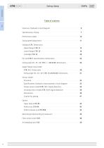
Swing clamp Swing clamp Structure, Hydraulic circuit diagram ……………………………………………… 6 Specifications, Piping ……………………………………………………………… 7 Performance table ………………………………………………………………… 10 Swing speed adjustment ………………………………………………………… 11 Standard CTK Dimensions Upper flange CTK□U …………………………………………………………… 12 Lower flange CTK□B …………………………………………………………… 16 Cartridge CTK□N ……………………………………………………………… 20 Pin rod CTK-P Specifications, Dimensions …………………………………… 24 Swing angle 30° , 45° , 60°CTK□□-30/45/60 Dimensions ………………… 26 Upper flange, long stroke CTK□U-J Dimensions ………………………………………………………… 30 Swing angle 30°...
カタログの6ページ目を開く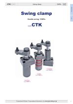
Swing clamp Double acting Swing clamp Swing clamp Double acting 35MPa Lower flange model Cartridge model Upper flange model To download CAD data / To get updated information, visit www.pascaleng.c
カタログの7ページ目を開く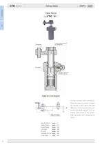
CTK□□ - □ Swing clamp Swing clamp Double acting Upper flange Positioning pin groove for clamp arm Hydraulic pressure (manifold piping) Hydraulic circuit diagram For flow control valve, we recommend the meter-in control. If meterout control is used, due to the area difference, it will cause back pressure and become high pressure. This can lead to malfunction of the system. Flow control valve model VCH (option) Please be aware when designing the circuit. Upper flange Lower flange Swing angle 30 , 45 , 60 page → 26 Long s
カタログの8ページ目を開く
Double acting Swing clamp Swing clamp Specifications Mounting and piping types Swing direction (when clamping), swing angle :Upper flange :Lower flange :Counter-clockwise, swing angle 90° :Counter-clockwise, swing angle 30° :Counter-clockwise, swing angle 45° :Counter-clockwise, swing angle 60° :Clockwise, swing angle 90° :Clockwise, swing angle 30° :Clockwise, swing angle 45° :Clockwise, swing angle 60° :Straight, swing angle 0° indicates made to order. Refer to pages →24 and 25 for details of pin rod (CTK□□-□P). Refer to pages →30 and 31 for details of long stroke of upper flange...
カタログの9ページ目を開く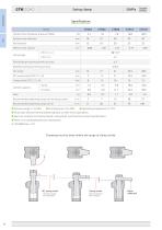
CTK□□ - □ Swing clamp Swing clamp Double acting Model Cylinder force (hydraulic pressure 35MPa) CTK Cylinder inner diameter Effective area (clamp) CTK□□-L, R Swing angle Positioning pin groove position accuracy Repeated clamp positioning accuracy Full stroke Clamp stroke (CTK□□-L, R) Cylinder capacity Mass Recommended tightening torque of mounting screws Recommended tightening torque of nut ● Fluid used:General mineral based hydraulic oil (ISO-VG32 equivalent) ● Seals are resistant to chlorine-based cutting fluid. (not thermal resistant specification) ● There is no overload protection...
カタログの10ページ目を開く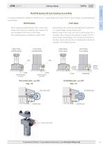
Double acting Swing clamp Swing clamp Manifold piping and G port piping are available. Two piping methods are available for model CTK□U-□ (upper flange) and model CTK□B-□ (lower flange), manifold piping and G port piping. When choosing manifold piping, a flow control valve Remove plugs when choosing G port piping for model CTK□ (model VCH) and an air bleeding valve (model VCE) U-□ (upper flange). (O-ring must be used.) are mountable on the G ports of the clamp. Remove plugs and O-ring, and mount sealing plug that is Only manifold piping is available for model CTK02. included, when choosing...
カタログの11ページ目を開くPascal Engineering Inc.のすべてのカタログと技術パンフレット
-
 Pascal auto coupler
60 ページ
-
 Mold clamping system
136 ページ
-
 Press machine system
48 ページ
-
 Stamping die clamping system
254 ページ
-
 Pascal N2 gas springs
28 ページ
-
 mini Gas springs
40 ページ
-
 N2 gas springs
86 ページ
-
 Expansion clamp
142 ページ
-
 air Work clamping system
130 ページ
-
 Pal system
106 ページ
-
 7MPa Work clamping system
256 ページ
-
 Pascal mag clamp
72 ページ