
カタログの抜粋

Modular Temperature Controller In-panel Temperature Controller with Flexible Modular Design and Wide Integration with Host Devices • The compact modular structure enables construction of temperature systems optimally suited to the application. • Connection can be made to a Programmable Controller without any programming required, reducing the number of steps required in ladder programming design. • One fully universal-input Unit includes a thermocouple, platinumresistance thermometer, and analog input for easy selection and reduced inventory requirements. • Connect directly to the G3ZA Multi-channel Power Controller using optimum cycle control for high-accuracy regulation with minimal noise. • Autotuning (AT) can be used for independent heating/cooling PID control. • Self-tuning (ST) can be used to calculate the PID constants with the step response method. • Up to 16 Temperature Controllers can be connected to a single DeviceNet Communications Unit. Supports DeviceNet Communications. Refer to the “Safety Precautions” on page 20. Ordering Information Temperature Controller Standard Control Models Power supply voltage Basic Unit (temperature control) *1 24 VDC 2 supplied from the End Unit 4 HFU with Programless Communications *1 Control outputs 1 and 2 Voltage output: 2 points (for SSR drive) *2 Control outputs 3 and 4 Transistor output: 2 points (sinking) Functions Auxiliary output None Voltage output: 2 points (for SSR drive) *2 Current output: 2 points Communications functions G3ZA connection port: RS-485 From End Unit: Port A or port B: RS-485 Transistor output: 2 points (sinking) Heater Event burnout inputs alarm 2 Input type Thermocouple, platinum resistance thermometer, analog voltage, and analog current selectable for each channel. Screw-less clamp Screw-less clamp Transistor output: 4 points (sinking) Screw-less clamp From End Unit: Port A: RS-485 Port C: RS-422 From End Unit: Port A: RS-485 HFU with DeviceNet Communications *1 Screw-less clamp Transistor output: 2 points (sinking) Screw-less clamp DeviceNet communications Screw-less clamp Port A or B: RS485 Connector: Port A Detachable connector *1. An End Unit is always required for connection to a Basic Unit or an HFU. An HFU cannot operate without a Basic Unit. External communications cannot be performed when using a Basic Unit only. *2. For heating/cooling control applications, control outputs 3 and 4 on the 2-point models are used for the cooling or heating control outputs. On the 4-point models, heating/cooling control is performed for the two input points. *3. When using the heater burnout alarm, purchase a Current Transformer (E54-CT1 or E54-CT3) separately. Functional Upgrades Refer to page 17 for details. Upgrade functions are supported by the indicated version ("V1.1" or "V1.2") or a higher version of the software. Refer to the following manual for precautionary information and other information necessary to use the EJ1: EJ1 Modular Temperature Controller User’s Manual (Cat. No. H142)
カタログの1ページ目を開く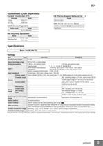
EJ1 Accessories (Order Separately) Current Transformer (CT) Diameter CX-Thermo Support Software Ver. 4.1 USB-Serial Conversion Cable G3ZA Connecting Cable Cable length Rail Mounting Equipment Name Mounting Rail Ratings Item Power supply voltage Operating voltage range Power consumption Thermocouple: ES1B Infrared Thermosensor: Analog input: Platinum resistance thermometer: Input impedance 4 W max. (at maximum load) K, J, T, E, L, U, N, R, S, B, W, PLII 10 to 70°C, 60 to 120°C, 115 to 165°C, 140 to 260°C 4 to 20 mA, 0 to 20 mA, 1 to 5 V, 0 to 5 V, 0 to 10 V Pt100, JPt100 Current input: 150 Ω...
カタログの2ページ目を開く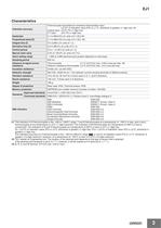
EJ1 Characteristics Indication accuracy Thermocouple input/platinum resistance thermometer input: (±0.5% of indication value (PV) or ±1°C, whichever is greater) ±1 digit max. *1 Analog input: ±0.5% FS ±1 digit max. CT input: ±5% FS ±1 digit max. Control period Manual reset value Alarm setting range −1,999 to 9,999 (decimal point position depends on input type) Sampling period Influence of signal source resistance Thermocouple: 0.1°C (0.2°F)/Ω max. (100 Ω max per line) *3 Platinum resistance thermometer: 0.4°C (0.8°F)/Ω max. (10 Ω max per line) Insulation resistance Dielectric strength 600...
カタログの3ページ目を開く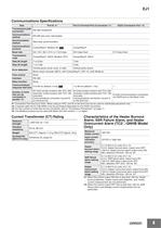
EJ1 Communications Specifications Port B *1 Port A Terminal/ Port A Connector *1 Transmission path RS-485 (multipoint) connection Communications method RS-485 (two-wire, half duplex) Synchronization method Start-stop synchronization Communications protocol Baud rate Transmission code CompoWay/F: ASCII, Modbus: RTU CompoWay/F: ASCII Vertical parity (none, even, or odd) Vertical parity (even) Error detection CompoWay/F 57.6 kbps fixed Block check character (BCC): with CompoWay/F, CRC-16: (with Modbus) Flow control Retry function Communications 0 to 99 ms (default: 5 ms) response wait time 64...
カタログの4ページ目を開く
EJ1 Input Ranges Sensor inputs are fully universal. Therefore, platinum resistance thermometer, thermocouple, infrared thermosensor, and analog input can be selected. Inputs can be set for each channel using universal inputs. Platinum resistance thermometer Input type Tempe rature range (°C) Setting number Input type Thermo couple Analog input Tempe rature range (°C) Any of the following ranges, by scaling: −1999 to 9999 −199.9 −199.9 to 999.9 to 999.9 −19.99 to 99.99 −1.999 to 9.999 Setting number Applicable standards by input type are as follows: K, J, T, E, N, R, S, B: JIS C1602-1995,...
カタログの5ページ目を開く
Ratings Power supply voltage Operating voltage range Power consumption Event inputs Transistor outputs Max. operating voltage: 30 VDC, Max. load current: 50 mA Auxiliary outputs Contact inputs Transistor inputs ON: residual voltage of 1.5 max., OFF: leakage current of 0.1 mA max. Outflow current: Approx. 4 mA (per contact) Downloading (EJ1 reads data from a PLC) Number of parameters that can be set: 1200 V1.2 Applicable PLCs Programless connection Number of parameters that can be set: 1200 V1.2 Uploading (EJ1 writes data to a PLC) OMRON: CS/CJ/NJ Series Mitsubishi Electric:...
カタログの6ページ目を開くOMRON/オムロンのすべてのカタログと技術パンフレット
-
 D4F
D4F8 ページ
-
 D4GS-N
11 ページ
-
 E4E2
E4E25 ページ
-
 Fiber Unit E32-LT/LD
4 ページ
-
 G9SE Series
20 ページ
-
 NX-SL/SI/SO
20 ページ
-
 G9SP
G9SP28 ページ
-
 G9SX-SM
24 ページ
-
 G9SX-SM/LM
9 ページ
-
 G9SX/G9SX-GS
49 ページ
-
 G9SX-LM
28 ページ
-
 G9SB
G9SB10 ページ
-
 G9SA
G9SA16 ページ
-
 DST1 Series
5 ページ
-
 WS02-CFSC1-E
3 ページ
-
 G9SA-300-SC
9 ページ
-
 K8AK-AS
12 ページ
-
 K8AK-AW
16 ページ
-
 K8AK-VS
12 ページ
-
 K8AK-VW
12 ページ
-
 K8AK-PH
12 ページ
-
 K8DS-PH
12 ページ
-
 K8AK-PM
16 ページ
-
 K8DS-PM
12 ページ
-
 K8AK-PA
12 ページ
-
 K8DS-PA
12 ページ
-
 K8AK-PW
12 ページ
-
 K8DS-PU
12 ページ
-
 K8DS-PZ
12 ページ
-
 K8AK-TS/PT
12 ページ
-
 K8AK-LS
12 ページ
-
 K8AK-TH
12 ページ
-
 K2CM
K2CM16 ページ
-
 SE
SE15 ページ
-
 SAO
SAO13 ページ
-
 APR-S
APR-S6 ページ
-
 XS5
XS525 ページ
-
 XS2
XS229 ページ
-
 F92A
F92A4 ページ
-
 GLS
GLS3 ページ
-
 TL-L
TL-L5 ページ
-
 V680 series
68 ページ
-
 V680S Series
68 ページ
-
 MY
MY35 ページ
-
 E3NC-L/-S
16 ページ
-
 61F-GPN-BT / -BC
5 ページ
-
 NE1A-SCPU Series
8 ページ
-
![NE1A-SCPU0[]-EIP](https://img.directindustry.com/pdf/repository_di/15954/ne1a-scpu0-eip-616667_1mg.jpg) NE1A-SCPU0[]-EIP
NE1A-SCPU0[]-EIP8 ページ
-
 NE0A-SCPU01
6 ページ
-
 LY
LY14 ページ
-
![G2R-[]-S](https://img.directindustry.com/pdf/repository_di/15954/g2r-s-616653_1mg.jpg) G2R-[]-S
G2R-[]-S11 ページ
-
 G7T
G7T7 ページ
-
 G2A
G2A9 ページ
-
 G2A-434
7 ページ
-
 G2AK
G2AK7 ページ
-
 MK-S
MK-S9 ページ
-
 MK-S(X)
12 ページ
-
 MM
MM17 ページ
-
 MMK
MMK14 ページ
-
 G4Q
G4Q6 ページ
-
 G7Z
G7Z9 ページ
-
 G7J
G7J10 ページ
-
 E4B
E4B12 ページ
-
 E4A-3K
9 ページ
-
 E4C-UDA
5 ページ
-
 E6H-C
E6H-C5 ページ
-
 E6F-C
E6F-C5 ページ
-
 E6D-C
E6D-C5 ページ
-
 E6B2-C
5 ページ
-
 E6A2-C
5 ページ
-
 NL
NL8 ページ
-
 VB
VB5 ページ
-
 SC
SC5 ページ
-
 D5F
D5F5 ページ
-
 D5A
D5A8 ページ
-
 E3S-GS3E4
3 ページ
-
 E3S-R
E3S-R11 ページ
-
 E3S-A
E3S-A21 ページ
-
 E3S-CL
9 ページ
-
 E3ZM-C
14 ページ
-
 E3T Data Sheet
26 ページ
-
 E3T Series
6 ページ
-
 G5 Series
59 ページ
-
 Sysmac Catalog
410 ページ
-
 VT-X700
6 ページ
-
 E5AC-T
8 ページ
-
 CP1
CP112 ページ
-
 CP1E
CP1E12 ページ
-
 MS4800
40 ページ
-
 VC-DL100
6 ページ
-
 FZ4 Series
42 ページ
-
 ZG2
ZG216 ページ
-
 ZS Series
32 ページ
-
 ZW Series
24 ページ
-
 E9NC-T
2 ページ
-
 Vision System FH series
54 ページ
-
 CompoNet
28 ページ
-
 Code Reader/OCR
24 ページ
-
 NT series
18 ページ
-
 Safety Controller G9SP
28 ページ
-
 Data Logger ZR-RX Series
12 ページ
-
 DeviceNet Safety System
30 ページ
-
 Switching Power Supplies
16 ページ
-
 Photomicro Sensors
7 ページ
-
 Displacement Sensors
4 ページ
-
 H8PS Cam Positioner
32 ページ
-
 FQ Vision Sensor
17 ページ
-
 E2EF
E2EF8 ページ
-
 FQ2 Smart camera
24 ページ


カタログアーカイブ
-
 SMART REMOTE I/O
12 ページ
-
 Sensor Accessories
38 ページ
-
 REGULATION SOLUTIONS
24 ページ
-
 Vision Systems
20 ページ
