
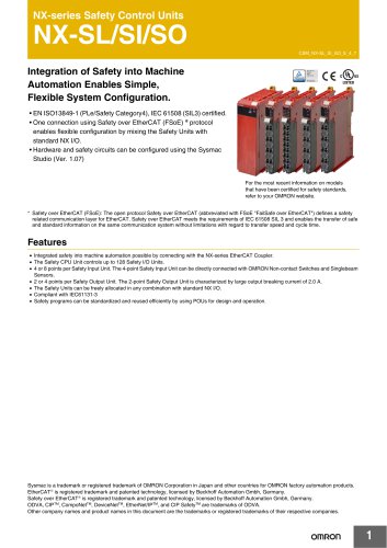
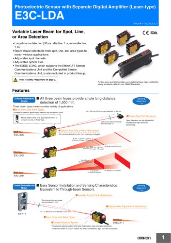
カタログの抜粋

Power Relay Stable Contact Reliability and Long Life • Easy to mount, wire, and use. • A large selection of models including various contact forms, DC-switching models, and open models. • Mechanical life: 5,000,000 operations; electrical life (under rated load): 500,000 operations. • Models also available with built-in diodes and for use as auxiliary power relays. Refer to Safety Precautions for All Relays. Ordering Information Type Contact form Open structure Solder terminals Screw terminals Plug-in (octal pins) terminals 4PDT DC-switching with built-in diode With built-in diode With operation indicator DC-switching with operation indicator Conforming to auxiliary power relay speci- 4PDT fications ■ Available Models Open Coils (with Solder Terminals) Type Standard Contact form Relay model Available rated voltage
カタログの1ページ目を開く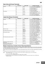
MM Open Coils (with Screw Terminals) Type Standard Contact form Relay model Available rated voltage Cased Coils (Plug-in Terminals) Type Standard Contact form Relay model Available rated voltage With built-in diode DC-switching with built-in diode With operation indicator Conforming to auxiliary power relay specifications Conforming to auxiliary power relay specifications for DC-switching DC-switching with operation indicator Models Conforming to Auxiliary Power Relay Specifications The MM4P-JD and MM4XP-JD satisfy the ratings of auxiliary relays provided in JEC-2500 (1987) standards for...
カタログの2ページ目を開く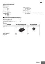
MM Model Number Legend MM@@@@-@ 1 4. Operation Indicator None: Not provided N: Provided 5. Built-in Diode None: Not provided D: Provided 1. Contact Form 2: DPDT 3: 3PDT 4: 4PDT 2. Type (See Note.) None: Standard X: DC-switching 3. Terminal Shape None: Solder B: Screw P: Plug-in Note: The suffix “JD” indicates models conforming to auxiliary power relay specifications. ■ Accessories (Order Separately) Mounting Brackets Mounting Bracket (S bracket) Sockets Relay model DIN Track/Front-connecting Socket (screw terminals) Back-connecting Socket (solder terminals)
カタログの3ページ目を開く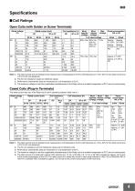
Specifications ■ Coil Ratings Open Coils (with Solder or Screw Terminals) Rated voltage (V) Mustrelease voltage Mustoperate voltage Note: 1. The rated current and coil resistance are measured at a coil temperature of 23°C with tolerances of +15%/–20% for AC rated current and ±15% for DC coil resistance. 2. The AC coil resistance values are reference values. 3. Performance characteristic data are measured at a coil temperature of 23°C. 4. The maximum voltage is one that is applicable instantaneously to the Relay coil at an ambient temperature of 23°C and not continuously. Cased Coils...
カタログの4ページ目を開く
MM Coils (Conforming to Auxiliary Power Relay Specifications) Rated voltage (V) Coil Coil inductance (H) resistance (Ω) Contact release Contact operate Opera- Power consumption tion level (VA or W) (JEC174D) Initial Rated Mustrelease voltage Mustoperate voltage B Hot start after coil heated Note: 1. The rated current and coil resistance are measured at a coil temperature of 23°C with tolerances of +15%/–20% for AC rated current and ±15% for DC coil resistance. 2. The AC coil resistance and coil inductance values are for reference only. 3. Performance characteristic data are measured at a...
カタログの5ページ目を開く
MM Contacts (Conforming to Auxiliary Power Relay Specifications) Item Inductive load (cosφ = 0.4, L/R = 7 ms) Contact type Rated load Rated carry current Max. switching power (reference value) Inductive load (cosφ = 0.4, L/R = 7 ms) Contact material Resistive load Note: 1. A model for DC loads is not in stable operation when switching an inductive load within a operating current range between 0.5 and 2.5 A at a minimum of 125 VDC, where the load cannot be switched. 2. If L/R exceeds 7 ms when switching DC inductive loads, an arc-breaking time of up to 50 ms must be considered in application...
カタログの6ページ目を開く
MM Relays (Conforming to Auxiliary Power Relay Specifications) Item Cased Relays Contact resistance (See note 2.) Operate time (See note 3.) Release time (See note 3.) Mechanical: Electrical: 1,800 operations/hr 1,800 operations/hr (under rated load) Insulation resistance (See note 4.) Dielectric strength Between coil and contact: 2,000 VAC, 50/60 Hz for 1 minute Between contacts of different polarity: 2,000 VAC, 50/60 Hz for 1 minute Between contacts of same polarity: 1,500 VAC, 50/60 Hz for 1 minute Vibration resistance Destruction: 10 to 55 to 10 Hz, 0.75 mm single amplitude (1.5 mm...
カタログの7ページ目を開く
MM Endurance Curves Open Relays Cased Relays MM@P(N, -D) 220 VAC resistive load inductive load (cosφ = 0.4) 24 VDC resistive load inductive load L/R = 7 ms 5,000 220 VAC resistive load inductive load (cosφ = 0.4) 24 VDC resistive load inductive load L/R = 7 ms ■ DC-switching Relays Maximum Switching Power Open Relays Cased Relays Endurance Curves Open Relays Cased Relays 24 VDC resistive load 110 VDC resistive load 24 VDC resistive load 110 VDC resistive load
カタログの8ページ目を開く
■ Relays Conforming to Auxiliary Power Relay Specifications Maximum Switching Power
カタログの9ページ目を開く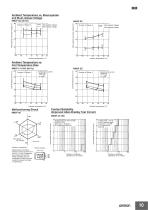
MM Ambient Temperature vs. Must-operate and Must-release Voltage MM2P DC Must-operate voltage Must-release voltage Must-operate and reset voltage (%) Must-operate and reset voltage (%) Must-operate voltage Must-release voltage Ambient Temperature vs. Coil Temperature Rise MM2P DC Coil temperature rise (° C) Coil temperature rise ( ° C) MM2P 110 VAC (60 Hz) Contact carry current Contact carry current Contact Reliability (Improved Allen-Bradley Test Circuit) Number of samples: 5 Measurement conditions: Impose a shock of 100 m/s2 in the ±X, ±Y, and ±Z directions three times each with the Relay...
カタログの10ページ目を開く
MM Relay Mounting Adjacent Distance vs. Coil Temperature Rise Coil temperature rise ( ° C) MM4P 100 /(110) VAC Relay mounting position Condition: The saturated coil temperature is measured with the rated carry current (7.5 A) at the rated coil voltage (100 VAC at 50 Hz). Contact carry current (7.5 A) No contact carry current Average of No. 2, 4, 6, and 8 Average of No. 1, 3, 7, and 9 Mounting adjacent distance l (mm) Dimensions Note: All units are in millimeters unless otherwise indicated. ■ Standard Relays Open Relays Solder Terminals MM2(X), MM4(X), MM3(X) Four, M4 mounting screw holes...
カタログの11ページ目を開くOMRON/オムロンのすべてのカタログと技術パンフレット
-
 D4F
D4F8 ページ
-
 D4GS-N
11 ページ
-
 E4E2
E4E25 ページ
-
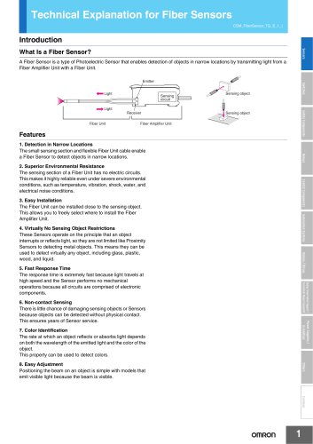
 Fiber Unit E32-LT/LD
4 ページ
-
 G9SE Series
20 ページ
-
 NX-SL/SI/SO
20 ページ
-
 G9SP
G9SP28 ページ
-
 G9SX-SM
24 ページ
-
 G9SX-SM/LM
9 ページ
-
 G9SX/G9SX-GS
49 ページ
-
 G9SX-LM
28 ページ
-
 G9SB
G9SB10 ページ
-
 G9SA
G9SA16 ページ
-
 DST1 Series
5 ページ
-
 WS02-CFSC1-E
3 ページ
-
 G9SA-300-SC
9 ページ
-
 K8AK-AS
12 ページ
-
 K8AK-AW
16 ページ
-
 K8AK-VS
12 ページ
-
 K8AK-VW
12 ページ
-
 K8AK-PH
12 ページ
-
 K8DS-PH
12 ページ
-
 K8AK-PM
16 ページ
-
 K8DS-PM
12 ページ
-
 K8AK-PA
12 ページ
-
 K8DS-PA
12 ページ
-
 K8AK-PW
12 ページ
-
 K8DS-PU
12 ページ
-
 K8DS-PZ
12 ページ
-
 K8AK-TS/PT
12 ページ
-
 K8AK-LS
12 ページ
-
 K8AK-TH
12 ページ
-
 K2CM
K2CM16 ページ
-
 SE
SE15 ページ
-
 SAO
SAO13 ページ
-
 APR-S
APR-S6 ページ
-
 XS5
XS525 ページ
-
 XS2
XS229 ページ
-
 F92A
F92A4 ページ
-
 GLS
GLS3 ページ
-
 TL-L
TL-L5 ページ
-
 V680 series
68 ページ
-
 V680S Series
68 ページ
-
 MY
MY35 ページ
-
 E3NC-L/-S
16 ページ
-
 61F-GPN-BT / -BC
5 ページ
-
 NE1A-SCPU Series
8 ページ
-
![NE1A-SCPU0[]-EIP](https://img.directindustry.com/pdf/repository_di/15954/ne1a-scpu0-eip-616667_1mg.jpg) NE1A-SCPU0[]-EIP
NE1A-SCPU0[]-EIP8 ページ
-
 NE0A-SCPU01
6 ページ
-
 LY
LY14 ページ
-
![G2R-[]-S](https://img.directindustry.com/pdf/repository_di/15954/g2r-s-616653_1mg.jpg) G2R-[]-S
G2R-[]-S11 ページ
-
 G7T
G7T7 ページ
-
 G2A
G2A9 ページ
-
 G2A-434
7 ページ
-
 G2AK
G2AK7 ページ
-
 MK-S
MK-S9 ページ
-
 MK-S(X)
12 ページ
-
 MMK
MMK14 ページ
-
 G4Q
G4Q6 ページ
-
 G7Z
G7Z9 ページ
-
 G7J
G7J10 ページ
-
 E4B
E4B12 ページ
-
 E4A-3K
9 ページ
-
 E4C-UDA
5 ページ
-
 E6H-C
E6H-C5 ページ
-
 E6F-C
E6F-C5 ページ
-
 E6D-C
E6D-C5 ページ
-
 E6B2-C
5 ページ
-
 E6A2-C
5 ページ
-
 NL
NL8 ページ
-
 VB
VB5 ページ
-
 SC
SC5 ページ
-
 D5F
D5F5 ページ
-
 D5A
D5A8 ページ
-
 E3S-GS3E4
3 ページ
-
 E3S-R
E3S-R11 ページ
-
 E3S-A
E3S-A21 ページ
-
 E3S-CL
9 ページ
-
 E3ZM-C
14 ページ
-
 E3T Data Sheet
26 ページ
-
 E3T Series
6 ページ
-
 G5 Series
59 ページ
-
 Sysmac Catalog
410 ページ
-
 VT-X700
6 ページ
-
 E5AC-T
8 ページ
-
 CP1
CP112 ページ
-
 CP1E
CP1E12 ページ
-
 MS4800
40 ページ
-
 VC-DL100
6 ページ
-
 FZ4 Series
42 ページ
-
 ZG2
ZG216 ページ
-
 ZS Series
32 ページ
-
 ZW Series
24 ページ
-
 E9NC-T
2 ページ
-
 Vision System FH series
54 ページ
-
 CompoNet
28 ページ
-
 Code Reader/OCR
24 ページ
-
 NT series
18 ページ
-
 Safety Controller G9SP
28 ページ
-
 Data Logger ZR-RX Series
12 ページ
-
 DeviceNet Safety System
30 ページ
-
 Switching Power Supplies
16 ページ
-
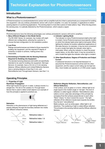
 Photomicro Sensors
7 ページ
-
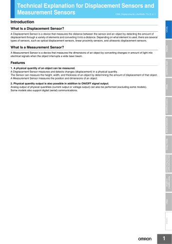
 Displacement Sensors
4 ページ
-
 H8PS Cam Positioner
32 ページ
-
 FQ Vision Sensor
17 ページ
-
 E2EF
E2EF8 ページ
-
 FQ2 Smart camera
24 ページ


カタログアーカイブ
-
 SMART REMOTE I/O
12 ページ
-
 Sensor Accessories
38 ページ
-
 REGULATION SOLUTIONS
24 ページ
-
 Vision Systems
20 ページ
