
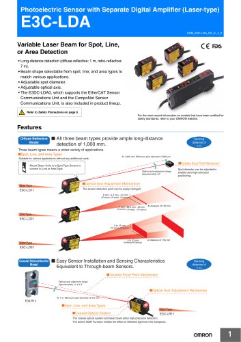
カタログの抜粋

General-purpose Relays New Super MK Relays. Models with Latching Lever Added to the Series. • Same mounting and internal wiring as the previous Super MK Relays • Built-in mechanical indicator enables checking contact operation. • Two modes can be used to check circuits for models with latching lever. • Nameplate provided on models with latching lever. • All materials are RoHS compliant. • UL and IEC (TÜV) certification. For the most recent information on models that have been certified for safety standards, refer to your OMRON website. Features Models with Latching Lever Operating Method for Latching Lever Operation indicator * Relay in Normal Operation Slide the latching lever to the first position, then press the yellow button with an insulated tool to operate the contact. Slide the latching lever to the second position. (The contact is now in the locked position.) Mechanical indicator Latching lever DC: Blue AC: Red Yellow button * The operation indicator is built in only on specified models. Example of Applications of Models with Latching Levers Operation checks in relay sequence circuits Model Number Structure Model Number Legend MKS@@@@@-@-@ 1 2 3 4 5 5. Coil Polarity Blank: Standard 1: Reverse polarity (DC coil only) 6. Surge Absorption Blank: Standard D: Surge absorber diode (DC coil only) V: Surge absorber varistor (AC coil only) 3. Mechanical Indicator/Test Button Blank: Mechanical indicator I: Mechanical indicator and lockable test button 4. LED Indicator Blank: Standard N: LED indicator 7. Internal Connections Blank: Standard 2 or 5: Non-standard connections (Refer to “Terminal Arrangement and Internal Connection (Bottom View)”.) 8. Rated Voltage (Refer to “Coil Ratings”.)
カタログの1ページ目を開く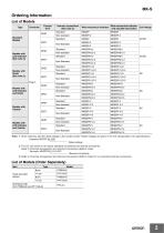
Ordering Information List of Models Type Contact form Internal connections (See note 3.) With mechanical indicator With mechanical indicator Coil ratings and lockable test button DPDT Models with LED Indicator (See note 2.) Standard Models Standard Standard DPDT Models with Varistor 3PDT Standard Standard DPDT Models with LED Indicator and Varistor Standard Standard Models with LED Indicator and Diode DPDT Models with Diode (See note 2.) Note: 1. When ordering, add the rated voltage to the model number. Rated voltages are given in the coil ratings table in the specifications. Example: MKS3P...
カタログの2ページ目を開く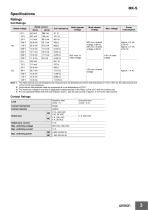
Specifications Ratings Coil Ratings Rated current Rated voltage Coil resistance Approx. 2.3 VA at 60 Hz Approx. 2.7 VA at 50 Hz 110% of rated voltage 30% min. of rated voltage at 60 Hz 25% min. of rated voltage at 50 Hz Power consumption Must release voltage Must operate voltage 125 V 10.8 mA 11,576 Ω The rated current and coil resistance are measured at a coil temperature of 23°C with tolerances of +15%/−20% for AC rated current and ±15% for DC coil resistance. Performance characteristic data are measured at a coil temperature of 23°C. The maximum voltage is one that is applicable...
カタログの3ページ目を開く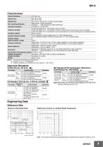
MK-S Characteristics Contact resistance 100 mΩ max. AC: 20 ms max. Operate time DC: 30 ms max. Release time 20 ms max. (40 ms max. for built-in Diode Relays) Mechanical: 18,000 operations/h Max. operating frequency Electrical: 1,800 operations/h (under rated load) Insulation resistance 100 MΩ min. (at 500 VDC) 2,500 VAC 50/60 Hz for 1 min between coil and contacts Dielectric strength 1,000 VAC 50/60 Hz for 1 min between contacts of same polarity and terminals of the same polarity 2,500 VAC 50/60 Hz for 1 min between current-carrying parts, non-current-carrying parts, and opposite polarity...
カタログの4ページ目を開く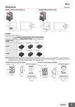
Models without Latching Lever Models with Latching Lever Sockets See below for Socket dimensions. Socket Maximum carry current Surface-mounting Socket (for track or screw mounting) Finger-protection models 10 A Note: Use the Surface-mounting Sockets (i.e., finger-protection models) with “-E” at the end of the model number. When using the PF083A and PF113A, be sure not to exceed the Socket's maximum carry current of 5 A. Using at a current exceeding 5 A may lead to burning. Round terminals cannot be used for finger-protection models. Use Y-shaped terminals. PF113A-E (Conforming to EN 50022)...
カタログの5ページ目を開く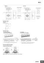
Terminal Arrangement Mounting Holes Mounting Holes Hold-down Clips Mounting Tracks * This dimension applies to the PFP-50N Mounting Track. * A total of twelve 25 × 4.5 elliptic holes is provided with six holes cut from each track end at a pitch of 10 mm. Mounting Height with Sockets Surface-mounting Sockets Three poles Note: PF083A(-E) and PF113A(-E) allow either track or screw mounting.
カタログの6ページ目を開く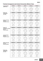
Terminal Arrangement and Internal Connection (Bottom View) Standard Models (AC/DC Coil) Models with Models with Diode Standard Polarity) Models with Reverse Polarity) Standard Models Standard Polarity) Models with Diode Reverse Polarity) Models with
カタログの7ページ目を開く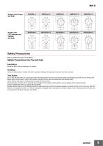
Models with Varistor (AC Coil) Models with LED indicator and Varistor (AC Coil) Safety Precautions Refer to Safety Precautions for All Relays. Safety Precautions for Correct Use Installation Mount the MK-S with the marking at the bottom. Handling Check the coil polarity of models with built-in operation indicator (DC operation coil) and wire them correctly . Test Button Do not use the test button for any purpose other than testing. Be sure not to touch the test button accidentally as this will turn the contacts ON. Before using the test button, confirm that circuits, the load, and any other...
カタログの8ページ目を開く
Read and Understand This Catalog Please read and understand this catalog before purchasing the products. Please consult your OMRON representative if you have any questions or comments. Warranty and Limitations of Liability WARRANTY OMRON's exclusive warranty is that the products are free from defects in materials and workmanship for a period of one year (or other period if specified) from date of sale by OMRON. OMRON MAKES NO WARRANTY OR REPRESENTATION, EXPRESS OR IMPLIED, REGARDING NON-INFRINGEMENT, MERCHANTABILITY, OR FITNESS FOR PARTICULAR PURPOSE OF THE PRODUCTS. ANY BUYER OR USER...
カタログの9ページ目を開くOMRON/オムロンのすべてのカタログと技術パンフレット
-
 D4F
D4F8 ページ
-
 D4GS-N
11 ページ
-
 E4E2
E4E25 ページ
-
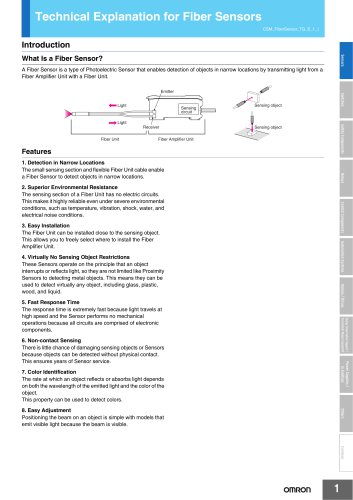
 Fiber Unit E32-LT/LD
4 ページ
-
 G9SE Series
20 ページ
-
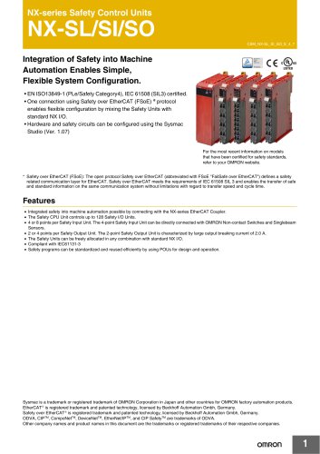 NX-SL/SI/SO
20 ページ
-
 G9SP
G9SP28 ページ
-
 G9SX-SM
24 ページ
-
 G9SX-SM/LM
9 ページ
-
 G9SX/G9SX-GS
49 ページ
-
 G9SX-LM
28 ページ
-
 G9SB
G9SB10 ページ
-
 G9SA
G9SA16 ページ
-
 DST1 Series
5 ページ
-
 WS02-CFSC1-E
3 ページ
-
 G9SA-300-SC
9 ページ
-
 K8AK-AS
12 ページ
-
 K8AK-AW
16 ページ
-
 K8AK-VS
12 ページ
-
 K8AK-VW
12 ページ
-
 K8AK-PH
12 ページ
-
 K8DS-PH
12 ページ
-
 K8AK-PM
16 ページ
-
 K8DS-PM
12 ページ
-
 K8AK-PA
12 ページ
-
 K8DS-PA
12 ページ
-
 K8AK-PW
12 ページ
-
 K8DS-PU
12 ページ
-
 K8DS-PZ
12 ページ
-
 K8AK-TS/PT
12 ページ
-
 K8AK-LS
12 ページ
-
 K8AK-TH
12 ページ
-
 K2CM
K2CM16 ページ
-
 SE
SE15 ページ
-
 SAO
SAO13 ページ
-
 APR-S
APR-S6 ページ
-
 XS5
XS525 ページ
-
 XS2
XS229 ページ
-
 F92A
F92A4 ページ
-
 GLS
GLS3 ページ
-
 TL-L
TL-L5 ページ
-
 V680 series
68 ページ
-
 V680S Series
68 ページ
-
 MY
MY35 ページ
-
 E3NC-L/-S
16 ページ
-
 61F-GPN-BT / -BC
5 ページ
-
 NE1A-SCPU Series
8 ページ
-
![NE1A-SCPU0[]-EIP](https://img.directindustry.com/pdf/repository_di/15954/ne1a-scpu0-eip-616667_1mg.jpg) NE1A-SCPU0[]-EIP
NE1A-SCPU0[]-EIP8 ページ
-
 NE0A-SCPU01
6 ページ
-
 LY
LY14 ページ
-
![G2R-[]-S](https://img.directindustry.com/pdf/repository_di/15954/g2r-s-616653_1mg.jpg) G2R-[]-S
G2R-[]-S11 ページ
-
 G7T
G7T7 ページ
-
 G2A
G2A9 ページ
-
 G2A-434
7 ページ
-
 G2AK
G2AK7 ページ
-
 MK-S(X)
12 ページ
-
 MM
MM17 ページ
-
 MMK
MMK14 ページ
-
 G4Q
G4Q6 ページ
-
 G7Z
G7Z9 ページ
-
 G7J
G7J10 ページ
-
 E4B
E4B12 ページ
-
 E4A-3K
9 ページ
-
 E4C-UDA
5 ページ
-
 E6H-C
E6H-C5 ページ
-
 E6F-C
E6F-C5 ページ
-
 E6D-C
E6D-C5 ページ
-
 E6B2-C
5 ページ
-
 E6A2-C
5 ページ
-
 NL
NL8 ページ
-
 VB
VB5 ページ
-
 SC
SC5 ページ
-
 D5F
D5F5 ページ
-
 D5A
D5A8 ページ
-
 E3S-GS3E4
3 ページ
-
 E3S-R
E3S-R11 ページ
-
 E3S-A
E3S-A21 ページ
-
 E3S-CL
9 ページ
-
 E3ZM-C
14 ページ
-
 E3T Data Sheet
26 ページ
-
 E3T Series
6 ページ
-
 G5 Series
59 ページ
-
 Sysmac Catalog
410 ページ
-
 VT-X700
6 ページ
-
 E5AC-T
8 ページ
-
 CP1
CP112 ページ
-
 CP1E
CP1E12 ページ
-
 MS4800
40 ページ
-
 VC-DL100
6 ページ
-
 FZ4 Series
42 ページ
-
 ZG2
ZG216 ページ
-
 ZS Series
32 ページ
-
 ZW Series
24 ページ
-
 E9NC-T
2 ページ
-
 Vision System FH series
54 ページ
-
 CompoNet
28 ページ
-
 Code Reader/OCR
24 ページ
-
 NT series
18 ページ
-
 Safety Controller G9SP
28 ページ
-
 Data Logger ZR-RX Series
12 ページ
-
 DeviceNet Safety System
30 ページ
-
 Switching Power Supplies
16 ページ
-
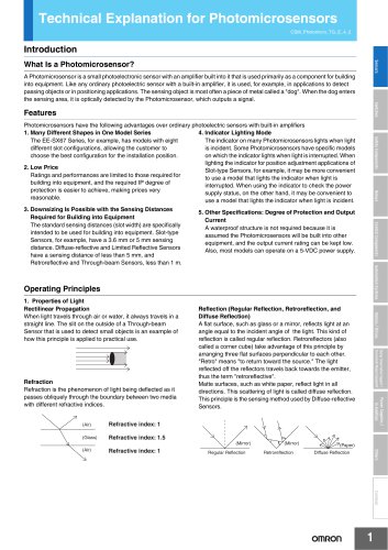
 Photomicro Sensors
7 ページ
-
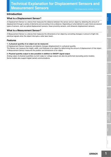
 Displacement Sensors
4 ページ
-
 H8PS Cam Positioner
32 ページ
-
 FQ Vision Sensor
17 ページ
-
 E2EF
E2EF8 ページ
-
 FQ2 Smart camera
24 ページ


カタログアーカイブ
-
 SMART REMOTE I/O
12 ページ
-
 Sensor Accessories
38 ページ
-
 REGULATION SOLUTIONS
24 ページ
-
 Vision Systems
20 ページ
