
カタログの抜粋

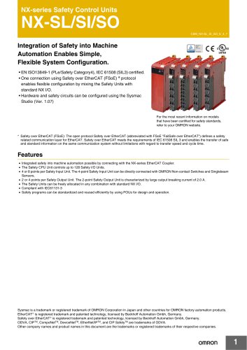
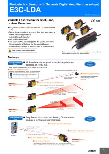
Logical AND Function Adds Flexibility to Various Safety Circuits A Be sure to read the “Safety Precautions” on page 45. For the most recent information on models that have been certified for safety standards, refer to your OMRON website. Unit Variation Non-Contact Door Switch Controller G9SX-NS □ D40A/D40Z input □ 2 Instantaneous safety outputs □ 1 Logical AND connection input G9SX-BC □ 2 Safety inputs □ 2 Instantaneous safety outputs G9SX-AD □ 2 Safety inputs □ 3 Instantaneous safety outputs □ 2 Safety off-delayed outputs G9SX-ADA □ 2 Safety inputs □ 2 Instantaneous safety outputs □ 2 Safety off-delayed outputs G9SX-EX401 □ 4 Safety outputs (relay outputs) □ Synchronized to the instantaneous safety output of the advanced unit G9SX-EX041-T □ 4 Safety outputs (relay outputs) □ Synchronized to the off-delayed safety output of the advanced unit G9SX-GS □ Automatic switching function □ Manual switching function G9SX-NSA □ No. of input channels of D40A/D40Z and mechanical safety door switch: 1 or 2 channels □ 2 Instantaneous safety outputs □ 2 Safety off-delayed outputs For details on G9SX, refer to page 2 and the subsequent pages. For details on G9SX-GS, Note. For details on G9SX-NS/NSA, refer to D40A refer to page 21 and the Compact Non-Contact Door Switch Catalog subsequent pages. (Cat. No. C140).
カタログの1ページ目を開く
Flexible Safety Unit G9SX Logical AND Function Adds Flexibility to I/O Expansion • Facilitates partial or complete control system setup. • Solid-state outputs (excluding Expansion Units). • Detailed LED indications enable easy diagnosis. • TÜV SÜD certification for compliance with IEC/EN61508 (SIL3), EN ISO13849-1 (PLe/Safety Category 4). • Approved by UL and CSA. Be sure to read the “Safety Precautions” on page 45. For the most recent information on models that have been certified for safety standards, refer to your OMRO
カタログの2ページ目を開く
Application Examples Parts Processing Machine • The entire device stops when the emergency stop switch is pressed. • Only the processing section stops when the Safety Light Curtain is interrupted. (2) Safety Light Curtain (1) Emergency stop switch (1) Emergency stop switch (2) Safety Light Curtain Basic Unit G9SX-BC Operating Example (1) The emergency stop switch is pressed. (2) Safety Light Curtain is interrupted. Stop Stop Segment A Machining Center • When the Emergency Stop Switch is pressed, the entire machine will stop. • When a door is open, the corresponding part will not be...
カタログの3ページ目を開く
Semiconductor Manufacturing Equipment • All of the equipment stops when the emergency stop switch is pressed. • The processing section and conveyor section stop when the processing section cover is opened. • Only the conveyor section stops when the conveyor section cover is opened. (2) Processing section cover (3) Conveyor section cover (3) Conveyor section cover Safety Door Switch Safety Door Switch (1) Emergency stop switch (2) Processing section cover (1) Emergency stop switch Operating Example (2) The processing section cover is opened. (1) The emergency stop switch is pressed. Stop...
カタログの4ページ目を開く
Model Number Legend Note: Please see “Ordering Information” below for the actual models that can be ordered. 4. Output Configuration (Auxiliary Outputs) 1: 1 output 2: 2 outputs 5. Max. OFF-delay Time Advanced Unit T15: 15 s T150: 150 s Basic Unit No indicator: No OFF delay Expansion Unit No indicator: No OFF delay T: OFF delay 6. Terminal Block Type RT: Screw terminals RC: Spring-cage terminals 1. Functions AD/ADA: Advanced Unit BC: Basic Unit EX: Expansion Unit Advanced Unit *1. P channel MOS-FET output *2. PNP transistor output Expansion Unit Safety outputs *1. PNP transistor output...
カタログの5ページ目を開く
Accessories Terminal Block
カタログの6ページ目を開く
*1. When two or more Units are connected by logical AND, the operating time and response time are the sum total of the operating times and response times, respectively, of all the Units connected by logical AND. *2. Represents the operating time when the safety input turns ON with all other conditions set. *3. Represents the operating time when the logical AND input turns ON with all other conditions set. *4. This does not include the operating time or response time of Advanced Units that are connected. *5. This does not include the operating time or response time of internal relays in the...
カタログの7ページ目を開く
Logical AND Connection Item Model Note: See Logical AND Connection Combinations below for details. *1. The number of G9SX-EX401-D Expansion Units or G9SX-EX041-T-D Expansion Units (OFF-delayed Model) not included. *2. G9SX-EX401-D Expansion Units and G9SX-EX041-T-D Expansion Units (OFF-delayed Model) can be mixed. 5. Two logical AND connection outputs, each from different Advanced/Basic Units, can be logical AND connected to a single G9SX-ADA Unit. Logical AND Connection Combinations 1. One logical AND connection output from an Advanced Unit G9SX-AD can be logical AND connected to up to...
カタログの8ページ目を開く
G9SX Response Time and Operating Time The following table shows the response time for two or more Units that are logical AND connected. *1. The maximum response time (not including Expansion Units) in this block flow diagram is the time it takes the output from the Unit on the lowest tier to switch from ON to OFF after the input to the Unit on the highest tier switches from ON to OFF. *2. The maximum response time (including Expansion Units) in this block flow diagram is the time it takes the output from the Expansion Unit connected to the Unit on the lowest tier to switch from ON to OFF...
カタログの9ページ目を開く
Wiring of Inputs and Outputs Safety input 1 Instantaneous safety output OFF-delayed safety output Logical AND connection output Auxiliary monitor output Auxiliary error output Signal name Power supply input Feedback/reset input Logical AND connection input Cross fault detection input Keep these outputs open when not used. Keep these outputs open when not used. Keep these outputs open when not used. Keep these outputs open when not used. Keep these outputs open when not used. Wiring Connect the power supply plus (24 VDC) to the A1 terminal. Connect the power supply minus (GND) to the...
カタログの10ページ目を開くOMRON/オムロンのすべてのカタログと技術パンフレット
-
 D4F
D4F8 ページ
-
 D4GS-N
11 ページ
-
 E4E2
E4E25 ページ
-
 Fiber Unit E32-LT/LD
4 ページ
-
 G9SE Series
20 ページ
-
 NX-SL/SI/SO
20 ページ
-
 G9SP
G9SP28 ページ
-
 G9SX-SM
24 ページ
-
 G9SX-SM/LM
9 ページ
-
 G9SX-LM
28 ページ
-
 G9SB
G9SB10 ページ
-
 G9SA
G9SA16 ページ
-
 DST1 Series
5 ページ
-
 WS02-CFSC1-E
3 ページ
-
 G9SA-300-SC
9 ページ
-
 K8AK-AS
12 ページ
-
 K8AK-AW
16 ページ
-
 K8AK-VS
12 ページ
-
 K8AK-VW
12 ページ
-
 K8AK-PH
12 ページ
-
 K8DS-PH
12 ページ
-
 K8AK-PM
16 ページ
-
 K8DS-PM
12 ページ
-
 K8AK-PA
12 ページ
-
 K8DS-PA
12 ページ
-
 K8AK-PW
12 ページ
-
 K8DS-PU
12 ページ
-
 K8DS-PZ
12 ページ
-
 K8AK-TS/PT
12 ページ
-
 K8AK-LS
12 ページ
-
 K8AK-TH
12 ページ
-
 K2CM
K2CM16 ページ
-
 SE
SE15 ページ
-
 SAO
SAO13 ページ
-
 APR-S
APR-S6 ページ
-
 XS5
XS525 ページ
-
 XS2
XS229 ページ
-
 F92A
F92A4 ページ
-
 GLS
GLS3 ページ
-
 TL-L
TL-L5 ページ
-
 V680 series
68 ページ
-
 V680S Series
68 ページ
-
 MY
MY35 ページ
-
 E3NC-L/-S
16 ページ
-
 61F-GPN-BT / -BC
5 ページ
-
 NE1A-SCPU Series
8 ページ
-
![NE1A-SCPU0[]-EIP](https://img.directindustry.com/pdf/repository_di/15954/ne1a-scpu0-eip-616667_1mg.jpg) NE1A-SCPU0[]-EIP
NE1A-SCPU0[]-EIP8 ページ
-
 NE0A-SCPU01
6 ページ
-
 LY
LY14 ページ
-
![G2R-[]-S](https://img.directindustry.com/pdf/repository_di/15954/g2r-s-616653_1mg.jpg) G2R-[]-S
G2R-[]-S11 ページ
-
 G7T
G7T7 ページ
-
 G2A
G2A9 ページ
-
 G2A-434
7 ページ
-
 G2AK
G2AK7 ページ
-
 MK-S
MK-S9 ページ
-
 MK-S(X)
12 ページ
-
 MM
MM17 ページ
-
 MMK
MMK14 ページ
-
 G4Q
G4Q6 ページ
-
 G7Z
G7Z9 ページ
-
 G7J
G7J10 ページ
-
 E4B
E4B12 ページ
-
 E4A-3K
9 ページ
-
 E4C-UDA
5 ページ
-
 E6H-C
E6H-C5 ページ
-
 E6F-C
E6F-C5 ページ
-
 E6D-C
E6D-C5 ページ
-
 E6B2-C
5 ページ
-
 E6A2-C
5 ページ
-
 NL
NL8 ページ
-
 VB
VB5 ページ
-
 SC
SC5 ページ
-
 D5F
D5F5 ページ
-
 D5A
D5A8 ページ
-
 E3S-GS3E4
3 ページ
-
 E3S-R
E3S-R11 ページ
-
 E3S-A
E3S-A21 ページ
-
 E3S-CL
9 ページ
-
 E3ZM-C
14 ページ
-
 E3T Data Sheet
26 ページ
-
 E3T Series
6 ページ
-
 G5 Series
59 ページ
-
 Sysmac Catalog
410 ページ
-
 VT-X700
6 ページ
-
 E5AC-T
8 ページ
-
 CP1
CP112 ページ
-
 CP1E
CP1E12 ページ
-
 MS4800
40 ページ
-
 VC-DL100
6 ページ
-
 FZ4 Series
42 ページ
-
 ZG2
ZG216 ページ
-
 ZS Series
32 ページ
-
 ZW Series
24 ページ
-
 E9NC-T
2 ページ
-
 Vision System FH series
54 ページ
-
 CompoNet
28 ページ
-
 Code Reader/OCR
24 ページ
-
 NT series
18 ページ
-
 Safety Controller G9SP
28 ページ
-
 Data Logger ZR-RX Series
12 ページ
-
 DeviceNet Safety System
30 ページ
-
 Switching Power Supplies
16 ページ
-
 Photomicro Sensors
7 ページ
-
 Displacement Sensors
4 ページ
-
 H8PS Cam Positioner
32 ページ
-
 FQ Vision Sensor
17 ページ
-
 E2EF
E2EF8 ページ
-
 FQ2 Smart camera
24 ページ


カタログアーカイブ
-
 SMART REMOTE I/O
12 ページ
-
 Sensor Accessories
38 ページ
-
 REGULATION SOLUTIONS
24 ページ
-
 Vision Systems
20 ページ
