カタログの抜粋
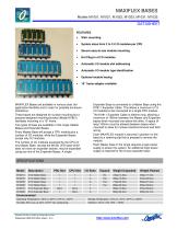
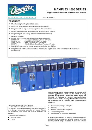
DATASHEET FEATURES • Wall- mounting System sizes from 2 to 15 I/O modules per CPU Secure easy-to-use module mounting. Automatic I/O module slot addressing Automatic I/O module type identification Optional module keying 19” frame adapter available MAXIFLEX Bases are available in various sizes (for application flexibility and to cater for possible enclosure limitations). These bases are designed for surface mounting but a purpose designed mounting bracket (Model M1821) facilitates mounting in a 19” frame. Two types of base are available in this range: Master Bases and Expander Bases. Every Master Base will accept a CPU module plus a number of I/O modules, while the Expander Bases accept only I/O modules. The number of I/O modules accessed by the CPU on any Master Base, (except the M1001 2I/O base which does not have an expander socket), may be expanded using any one of the Expander Bases. A single Expander Base is connected to a Master Base using the M1811 Expander Cable. This allows a maximum of 15 I/O modules to be connected to a single CPU module. The M1811 Expander Cable is 400mm long, allowing a maximum of 180mm between the Master and Expander bases when mounted one above the other. A space of least 100mm must be allowed between bases when mounted to allow for module insertion/removal and field wiring. Each MAXIFLEX module is secured in position on the base by a retaining clip that is pressed to remove the module. Each Master base in the range requires a logic power supply to power the system. An additional logic power supply is required for the 8 way expander base. SPECIFICATIONS Model Weight Unpacked Weight Packed Environmental Operating Temperature: -25°C to +60°C (-13°F to +140°F) Copyright Omniflex ♦ Subject to change without notice
カタログの1ページ目を開く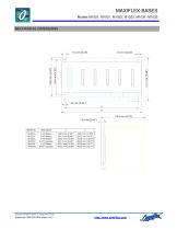
MECHANICAL DIMENSIONS 2 I/O Master 3 I/O Master 5 I/O Master 5 I/O Expander 7 I/O Master 8 I/O Expander Copyright Omniflex ♦ Subject to change without notice
カタログの2ページ目を開く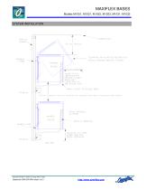
MAXIFLEX BASES SYSTEM INSTALLATION MAXIFLEX BASE CABINET ROOF CLEARANCE ABOVE MODULE REQUIRED FOR MODULE INSERTION/REMOVAL POSITION NETWORK CABLES WIRING ACCESS TO MODULES HERE 100 mm minimum (180 mm maximum for expansion base due to expansion cable length) MOUNT VERTICALLY WIRING CLEARANCE SIDE VIEW Copyright Omniflex ♦ Subject to change without notice
カタログの3ページ目を開くOmniflexのすべてのカタログと技術パンフレット
-
 MAXIFLEX Bases
3 ページ
-
 Model M1265A CPU A3e
8 ページ
-
 Model M1711A HSC
2 ページ
-
 Model M1322A 16DI-24
2 ページ
-
 Model M1323A 16DI-48
2 ページ
-
 Model M1326A 32DI-24
2 ページ
-
 Model M1327A 64DI-24
2 ページ
-
 Model M1341B 16DO
2 ページ
-
 Model M1330A 8DI8RO
2 ページ
-
 Model M1342A 32DO
2 ページ
-
 Model M1372A 8RO
2 ページ
-
 Maxilarm
15 ページ
-
 Model C2330B-11-0
6 ページ
-
 Model C2330B-12-0
6 ページ
-
 Model M1403A 16AI
2 ページ
-
 Model M1412A 8AO
2 ページ
-
 C2404B
4 ページ
-
 C118xB series
4 ページ
-
 Model M1240B CPU T2
6 ページ
-
 Model M1102A PSU
2 ページ
-
 Model M1023B BASE
3 ページ
-
 Model M1021B BASE
3 ページ
-
 Model C2462A OT LPD
12 ページ