
カタログの抜粋

od«t Odot Automation System Co., Ltd http:// www.odotautomation.com
カタログの1ページ目を開く
od«t Odot Automation System Co., Ltd Modbus-RTU/ASCll to ProfiNet Converter Odot Automation System Co., Ltd. 2018-03 Copyright ©2019 Odot Automation all rights reserved
カタログの2ページ目を開く
od«t Odot Automation System Co., Ltd Version Information The document has the following modifications:
カタログの3ページ目を開く
od«t Odot Automation System Co., Ltd Ownership rights information Without the permission of the copyright owner, all or part of this document shall not be republished as a paper or electronic document. Disclaimer This document is only intended to assist the reader in using the products, and the company shall not be responsible for any loss or error caused by the use of the information in this document. The product and text described in this document are under constant development and refinement. Odot Automation System Co., Ltd. has the right to modify this document without notifying users....
カタログの4ページ目を開く
Od*t Odot Automation System Co., Ltd Area 4 for input data. 2> GSD file 20190803 and above versions are applicable to ABB Profinet master station system. 3 > Firmware V1.6 and above version add function: when the gateway works in transparent transmission mode, When the serial port selects the master-slave response mode, it also supports the active data reporting function.
カタログの5ページ目を開く
http:// www.odotautomation.com
カタログの6ページ目を開く
od«t Odot Automation System Co., Ltd l.product description 1.1 Product Features ODOT-PNM02 gateway is a Modbus-RTU/ASCII to ProfiNet protocol converter. It can realize the conversion from Modbus-RTU/ASCII to ProfiNet protocol. Any device with RS485/RS232/RS422 interface supporting Modbus-RTU protocol can use this product to realize interconnection with industrial bus ProfiNet. Such as: PLC, DCS, distributed IO, frequency converter, motor start protection device, intelligent high and low voltage electrical appliances, electricity measuring device, intelligent field measuring equipment and...
カタログの7ページ目を開く
OCM Odot Automation System Co., Ltd ♦ Maximum slots: 50 ♦ Serial port isolation: optocoupler isolation, power isolation ♦ Number of serial ports: support dual serial port RS485/RS232 or single serial port RS422 ♦ Serial port terminal resistance: an external 120Q resistance is required. ♦ Serial protocol: Supports Modbus-RTU/ASCII Master > Modbus-RTU/ASCIIA Slave ♦ Serial port parameters: Support 1200-115200 baud rate, support none, odd, even parity ♦ Number of Modbus stations supported by serial port: 50 (limited by slot) ♦ Support Modbus function code: 01/02/03/04/05/06/15/16 ♦ Power...
カタログの8ページ目を開く
od«t Odot Automation System Co., Ltd Indicator light Modbus/Profinet Gateway ODOT-PNM02 Power Supply: 9-36 VDC Operating Temperature: -40~85“C Humidity: 5~95%RH (non-condensing) Symbol Description PWR: Power Status Odot Automation System Co LW g www.odotautomation com £ +86-816-2538289 The upper panel has two ProfiNet interfaces and power connection terminals. PORT1 and PORT2, the two interfaces have the same function. These two interfaces have the switch function, that is, the host computer can access the equipment connected to PORT2 through the PORT1 http:// www.odotautomation.com
カタログの9ページ目を開く
Od*t Odot Automation System Co., Ltd interface, as shown in the figure below (the computer IP is 192.168.1.92, the computer is connected to the PORT2 port, Siemens S7 -1200 connects to PORT1), the upper computer software can search for devices in the same ProfiNet Network. The front panel is a gateway serial port terminal. The serial port terminal is 2 serial ports when used for RS-232 communication or RS-485 communication, and 1 serial port when used for RS-422 communication. For specific definitions, see 2.3 Terminal Definitions. 2.2 Indicator light description The equipment has six LED...
カタログの10ページ目を開く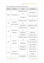
od«t Odot Automation System Co., Ltd and status description are shown in the table below.
カタログの11ページ目を開く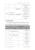
ocf-t Odot Automation System Co., Ltd
カタログの12ページ目を開く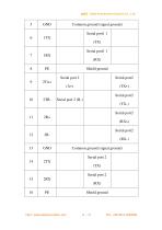
od«t Odot Automation System Co., Ltd
カタログの13ページ目を開く
od«t Odot Automation System Co., Ltd 2.4 External terminal resistance According to the actual situation on site, a 120Q terminal resistor needs to be connected to the serial port of the gateway. The RS485 bus supports a maximum of 32 nodes without relays. The nodes are connected by a "daisy chain" connection. Terminal resistors are required at both ends of the communication cable, and the resistance is required to be approximately equal to the characteristics of the transmission cable. impedance. In short-distance transmission, termination resistors are not required, that is, termination...
カタログの14ページ目を開く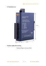
od«t Odot Automation System Co., Ltd Modbus/Profinet Gateway ODOT-PNM02 Power Supply: 9-36 VDC Operating Temperature: -40~85°C Humidity: 5-95%RH (non-condensing) Symbol Description PWR: Power Status C02 2#Senal Status Odot Automation System Co . Ltd g www.odotautomation.Mni £ +86-816-2538289 3.Product application topology Topology diagram of master Mode http:// www.odotautomation.com
カタログの15ページ目を開く
ocf-t Odot Automation System Co., Ltd Topology diagram of slave mode http:// www.odotautomation.com
カタログの16ページ目を開く
ocf-t Odot Automation System Co., Ltd 4.Firmware upgrade When the module firmware is updated, the module firmware needs to be upgraded. The upgrade needs to be performed in IAP mode. After pressing the reset button, power on the module with 24Vdc. When the SF and BF indicator lights flash red, it means entering the IAP module. Connect the 485 ports A and B of the USB to 485 converter to the 1TA+ and 1TB- ports of the gateway serial port 1, and connect the USB interface of the converter to the USB interface of the computer
カタログの17ページ目を開く
od*t Odot Automation System Co., Ltd Install the upgrade software: Firmware Update Tool V1.0.0.8 After the installation is complete, open the upgrade software, select the serial port of the interface, and then check the serial port number on my computer-"Device Manager". The baud rate is set to 115200. Click to read device information, you can read the internal firmware information of the gateway. Click on ■' , In the pop-up interface, select the new firmware file, click Open, and the new firmware information will be displayed in the lower left corner.
カタログの18ページ目を開くODOT Automationのすべてのカタログと技術パンフレット
-
 C3351
C33518 ページ
-
 BOXIO 64
4 ページ
-
 ODOT remote IO catalogue
20 ページ
-
 PLC
PLC59 ページ
-
 New small ODOT brochure
16 ページ
-
 CN-8034
2 ページ
-
 CN-8033
2 ページ
-
 CN-8032
2 ページ
-
 CN-8012
2 ページ
-
 CN-8011
2 ページ
-
 CN-8031
2 ページ
-
 Remote I/O C Series
376 ページ
-
 Remote I/O module
36 ページ
-
 CT-7221
17 ページ
-
 CT5800
15 ページ
-
 CT4234
20 ページ
-
 CT3804
21 ページ
-
 CT-3713
19 ページ
-
 CT3238
19 ページ
-
 CT-3158
19 ページ
-
 CT2718
18 ページ
-
 CT2228
18 ページ
-
 CT623F
23 ページ
-
 CT-222F
19 ページ
-
 CT-121F
21 ページ
-
 MG-IOT03 User Manual_V1
24 ページ
-
 ODOT-IOT02
44 ページ
-
 ODOT-S7PPIV2.0
31 ページ
-
 ODOT-PNM02
31 ページ
-
 ODOT-S4E2
56 ページ
-
 ODOT-IOT01
79 ページ


