カタログの抜粋

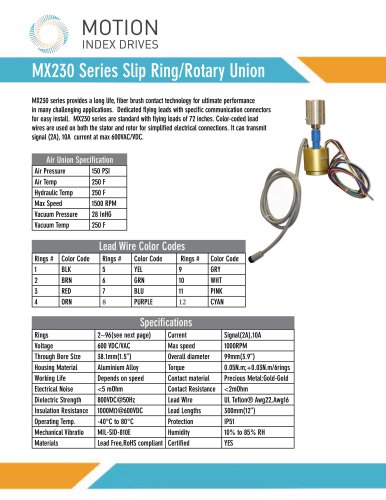
TT Series Rotary Indexer
カタログの1ページ目を開く
Fixed Index Drives The rotary index table transforms a constant input drive motion into an intermittent output drive motion. The intermittent drive motion occurs by means of a hardened and high accuracy barrel cam. The use of mathematical laws of motion guarantees a soft, shock-proof, and jerk free movement that has been optimally designed for its intended purpose. The design allows for accurate and secure mounting to the output dial. The preload of the cam to the cam followers in dwell ensures the top dial is backlash free. No additional adjustment of the output dial is necessary. The...
カタログの2ページ目を開く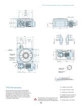
TT250 A = Length of input shaft B = Length of shaft to collar The dimensions shown here are the standard dimensions. The output flange, central column, housing and input shafts can be machined to your specifications. The central column can also be designed as a flange. Should you wish to drill additional holes, please consult us with regard to acceptable drilling depth. C = Diameter of input shaft D = Height of central column to supporting surface on output flange, standard is -0.5mm *All TT Series tables available in fixed or programmable formats. E = Flange plate as an option The...
カタログの3ページ目を開く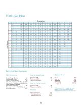
Load Table Scenarios Technical Specifications Main Dimensions Max. size of rotating plate 0 [mm] (other numbers on request) Index Table weight [kg] Direction Mounting Position Load on output flange Load on Central column Axial Runout [mm] Radial ±0.01 Standard Drive Motor Gear unit Motor size Voltage [V] The precision is 5 - 8 angular seconds greater at 16 or more indexes due to multiple dwell positions on the drive cam.
カタログの4ページ目を開く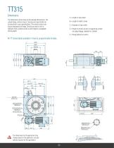
A = Length of input shaft The dimensions shown here are the standard dimensions. The output flange, central column, housing and input shafts can be machined to your specifications. The central column can also be designed as a flange. Should you wish to drill a dditional holes, please consult us with regard to acceptable drilling depth. B = Length of shaft to collar C = Diameter of input shaft D = Height of central column to supporting surface on output flange, standard is -0.5mm E = Flange plate as an option All TT Series tables available in fixed or programmable formats. Ø410 Ø360 Ø200h6...
カタログの5ページ目を開く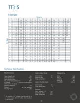
Load Table Scenarios Technical Specifications Main Dimensions Max. size of rotating plate 0 [mm] H 2800 (other numbers on request) Index Table weight [kg] 193 Load on output flange Load on Central column Standard Drive Gear unit Motor size Voltage [V] Power [kW] * The precision is 5 - 8 angular seconds greater at 16 or more indexes due to multiple dwell positions on the drive cam.
カタログの6ページ目を開く
INDEX DRIVES 1204 East Maple Troy MI 48083 P: 248-743-9999 F: 248-743-0749 info@mid.us.com www.motionindexdrives.com
カタログの7ページ目を開くMotion Index Drivesのすべてのカタログと技術パンフレット
-
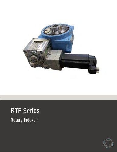 RTF Rotary Index Tables
13 ページ
-
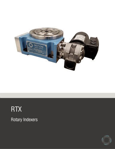 RTX Rotary Index Tables
20 ページ
-
 TSR Series
13 ページ
-
 Precision Link Conveyor
12 ページ
-
 Weld Positioner
5 ページ
-
 XP Series
23 ページ
-
 Pick and Place
5 ページ
-
 Product Catalog
152 ページ