カタログの抜粋

TSR Series Ring Index Drives - Circular Indexing
カタログの1ページ目を開く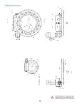
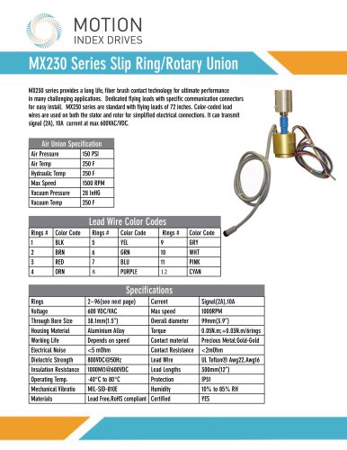
?INDEX DRIVES The Motion Index Drives TSR Series Rotary Indexing Ring Table encompasses a range of sizes that offer solutions for many applications. Four different models are available in our standard line: TSR600, TSR1000, TSR1400 and the TSR1900. Our Rotary Ring Index Drive are ideal for applications that require large, open center accessibility for tooling and other devices. The Rotary Indexing Ring Table can be manufactured with a fixed number of stations or as a flexible turntable with a servo motor or standard AC brake motor with encoder. ■ Easy synchronization of other mechanical...
カタログの2ページ目を開く
Variable drive concept
カタログの3ページ目を開く
Number and position of roller bolts dependent on pitch n48 The drive unit shown is an SEW brake motor of size IEC 90 Dimensions The dimensions shown here indicate the stan- If you would like to install the TSR vertically or in Attention! Never drill through the housing or the dard. Of course, we are happy to machine the out- a different position, please inform us so that we output ring. put ring according to your specifications. The can make the necessary changes. Attention! Depending on the drive size used, drive can also be designed with a servo motor or free shaft upon request.
カタログの4ページ目を開く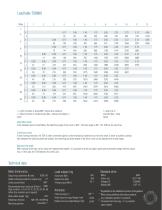
n = pitch (number of stops/360° output drive rotation) J = Mass moment of inertia (body plate + devices and steps) in kgm2 t = step time in seconds Step = Step speed Intermittent mode In the standard version (load table), the switching angle of the curve is 300°. The bosh angle is 60°. The TSR has its own drive. Continuous mode In fast-running machines, the TSR is often connected rigidly to other mechanical systems via a free drive shaft. In order to achieve a certain ratio between the switching and bosh phases, the switching and bosh angles of the drive curve can be adjusted over a wide...
カタログの5ページ目を開く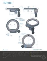
2xØ8H7x12 (auf Ø950±0.02) Number and position of roller bolts dependant on pitch Leave min. Ø70mm free from underside for roller bolt 25.5 The drive unit shown is an SEW brake motor of size IEC 90 Dimensions The dimensions shown here indicate the standard. If you would like to install the TSR vertically or Attention! Never drill through the housing or the Of course, we are happy to machine the output ring in a different position, please inform us so that output ring. according to your specifications. The drive can we can make the necessary changes. Attention! Depending on the drive size...
カタログの6ページ目を開く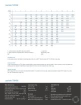
n = pitch (number of stops/360° output drive rotation) t = step time in J = Mass moment of inertia (body plate + devices and steps) in seconds Step = Step Intermittent mode In the standard version (load table), the switching angle of the curve is 300°. The bosh angle is 60°. The TSR has its own drive. Continuous mode In fast-running machines, the TSR is often connected rigidly to other mechanical systems via a free drive shaft. In order to achieve a certain ratio between the switching and bosh phases, the switching and bosh angles of the drive curve can be adjusted over a wide range. With a...
カタログの7ページ目を開く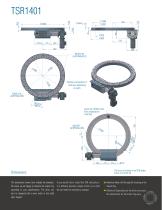
Number and position of roller pins depending on pitch Leave min. Ø70mm free from underside for roller bolt The drive unit shown is an SEW brake motor of size IEC 90 Dimensions The dimensions shown here indicate the standard. If you would like to install the TSR vertically or Attention! Never drill through the housing or the Of course, we are happy to machine the output ring in a different position, please inform us so that output ring. according to your specifications. The drive can we can make the necessary changes. Attention! Depending on the drive size used, also be designed with a servo...
カタログの8ページ目を開く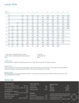
n = pitch (number of stops/360° output drive rotation) t = step time in J = Mass moment of inertia (body plate + devices and steps) in seconds Step = Step Intermittent mode In the standard version (load table), the switching angle of the curve is 300°. The bosh angle is 60°. The TSR has its own drive. Continuous mode In fast-running machines, the TSR is often connected rigidly to other mechanical systems via a free drive shaft. In order to achieve a certain ratio between the switching and bosh phases, the switching and bosh angles of the drive curve can be adjusted over a wide range. With a...
カタログの9ページ目を開く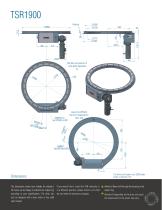
Number and position of roller bolts dependent on Leave min. Ø70mm free from underside for roller bolt 47 The drive unit shown is an SEW brake motor of size IEC 112 Dimensions The dimensions shown here indicate the standard. If you would like to install the TSR vertically or Attention! Never drill through the housing or the Of course, we are happy to machine the output ring in a different position, please inform us so that output ring. according to your specifications. The drive can we can make the necessary changes. Attention! Depending on the drive size used, also be designed with a servo...
カタログの10ページ目を開く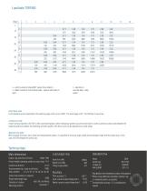
n = pitch (number of stops/360° output drive rotation) J = Mass moment of inertia (body plate + devices and steps) in kgm2 t = step time in seconds Step = Step speed Intermittent mode In the standard version (load table), the switching angle of the curve is 300°. The bosh angle is 60°. The TSR has its own drive. Continuous mode In fast-running machines, the TSR is often connected rigidly to other mechanical systems via a free drive shaft. In order to achieve a certain ratio between the switching and bosh phases, the switching and bosh angles of the drive curve can be adjusted over a wide...
カタログの11ページ目を開く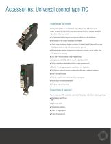
Properties and user benefits A rotary indexing table can be controlled in many different ways. With this universal control, we would like to provide you with a tool with which you can optimally operate the rotary table without much effort. ■ Cycle time optimisation through exact stopping of the drive in the bosh phase ■ Minimisation of the costs of installation and hardware ■ Simple integration through fieldbus connection (ProfiNet, EtherCAT, Ethernet/IP) and aids for integration (step-by-step instructions and video tutorials) ■ Motor protection switches and mechanical or electronic...
カタログの12ページ目を開くMotion Index Drivesのすべてのカタログと技術パンフレット
-
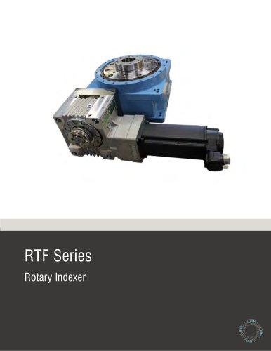 RTF Rotary Index Tables
13 ページ
-
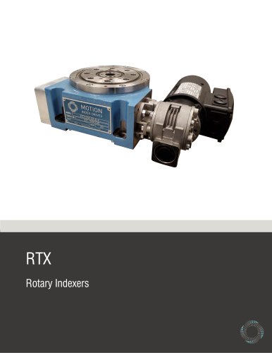 RTX Rotary Index Tables
20 ページ
-
 TT315 Series
7 ページ
-
 Precision Link Conveyor
12 ページ
-
 Weld Positioner
5 ページ
-
 XP Series
23 ページ
-
 Pick and Place
5 ページ
-
 Product Catalog
152 ページ