カタログの抜粋
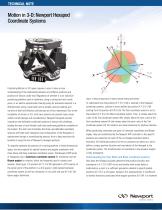
TECHNICAL NOTE Motion in 3-D: Newport Hexapod Coordinate Systems Controlling Motion in 3-D space requires a user to have a clear understanding of the relationship between end effector positions and positions of devices under test. Regardless of whether it is an industrial positioning platform used in machinery, using a cutting tool and a work piece, or an electro-optical beam steering setup for advanced research in a diffractometry using a laser beam and a sample, precise readings and controls of both end effectors and devices are of key importance. Due to the complexity of motion in 3-D, multi-axis systems can present many issues without careful design and considerations. Newport Hexapods provide innovative user-definable coordinate systems to answer this challenge, leading the way of user-friendly multi-axis positioning platforms available on the market. This tech note illustrates the three user-definable coordinate systems and helps with integration and configuration of the Hexapods in experimental setups or manufacturing process, thus to help maximize the benefits of using the line of Newport’s Hexapod products. To uniquely represent the position of a moving platform in three-dimensional space, one must specify its spatial location and angular orientation with three linear and three rotational coordinate values. The Newport HXP series of Hexapods uses a Cartesian coordinate system for translation and the Bryant angles for rotation, which are frequently used in robotics and aviation. (See Figure 1) A position (X Y Z U V W) represents a XYZ location of the center point of the platform in a 3-D space in right-handed Cartesian coordinate system as well as orientation in roll, pitch and yaw (U V W, TaitBryan angles definition). Figure 1: Setup Configuration for Optical Quality Testing with Gimbal To understand how the position (X Y Z U V W) is reached in the Hexapod coordinate systems, consider a move defined by position (X Y Z U V W) starting from the position (0 0 0 0 0 0). The Tool coordinate system is set to the position (X Y Z) in the Work coordinate system. Then, it rotates about the z axis of the Tool coordinate system (W), rotates about the new y axis of the Tool coordinate system (V) and rotates about the new x axis of the Tool coordinate system (U). All rotations are made clockwise for positive rotations. When positioning commands are given in Cartesian coordinates and Bryant angles, they are transformed by the Newport HXP controller to the specific positions and velocities for each of the six Hexapod actuators before execution. All individual positions for the six actuators are taken as a set to define a unique position (location and orientation) of the Hexapod in the coordinate system. The transformation of coordinate to the actuator lengths is fully transparent. Understanding the Tool, Work and Base coordinate systems How does the Hexapod uniquely determine the position (location and orientation in X Y Z U V W)? As we are familiar with scalar fields in mathematics, a point is a sufficient geometric element to specify spatial positions (X Y Z) in a 3-D space. However, this representation is insufficient to identify directions associated with angular positions (U V W). It is however
カタログの1ページ目を開く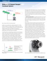
TECHNICAL NOTE Motion in 3-D: Newport Hexapod Coordinate Systems 0), the upper surface of the top plate is close to mid travel for the HXP50 and the HXP1000, and it is close to the lower extreme position for the HXP100); 3) The XY plane of the coordinate system is parallel to the base plate; 4) The W-axis (Yaw orientation) matches the orientation defined in the Hexapod drawing. (The motor cables point in the positive X-axis direction of the World coordinate system.) The World Coordinate System is an absolute fixed reference to the outside world. It is defined such that, in the default...
カタログの2ページ目を開く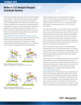
TECHNICAL NOTE Motion in 3-D: Newport Hexapod Coordinate Systems Why is the Base coordinate system defined relative to the World coordinate system, instead of the Work coordinate system? By referencing the World coordinate system, it is possible to take into account any change in the position of the Hexapod without affecting the motion commands of the Tool in the Work coordinate system. A good example is a Hexapod mounted on a moving platform at the center of a multi-axis goniometer in a diffractometry application. (Figure 4) When the Hexapod itself is rotated or moved to a different...
カタログの3ページ目を開く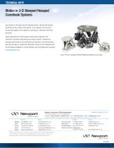
Motion in 3-D: Newport Hexapod Coordinate Systems axes relative to the beam from the starting position, allowing the material processing on the surface of the sample, as an example. This two pivot concept also applies to the inspection, metrology or traditional machining processes. Typical applications for the Hexapod include optical alignment and calibration, biomedical engineering and surgical robotics, satellite and telescope positioning, sensor metrology and calibration, and semiconductor test and metrology. For additional information, please visit the Newport HXP series Hexapod webpage...
カタログの4ページ目を開くMICRO-CONTROLE / Spectra-Physicsのすべてのカタログと技術パンフレット
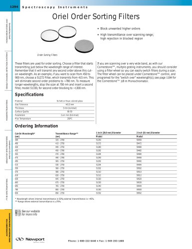
-
 Precision Motion Control
27 ページ
-
 SA2_90028936F
1 ページ
-
 10BPF10-370_ROHS
1 ページ
-
 10BPF10-320_ROHS
1 ページ
-
 10BPF10-310
1 ページ
-
 M-401
M-4011 ページ
-
 Tunable Diode Lasers
16 ページ
-
 newport ressource
1640 ページ
-
 Motion PL30
24 ページ
-
 CONEX-AG-LS25-27P
2 ページ
-
 Nanopositioners
40 ページ
-
 Beamsplitters
34 ページ
-
 Optrical mirror
33 ページ
-
 Fast Steering Mirrors
4 ページ
-
 Optical Delay Line Kit
1 ページ
-
 Long Scan Autocorrelator
1 ページ
-
 I-V Test Station
2 ページ
-
 Projects in Optics
2 ページ
-
 Air-Bearing System
2 ページ
-
 X-Ray Diffractometer
2 ページ
-
 Motion System
2 ページ
-
 Pick & Place Machine
2 ページ
-
 LabLegs™ Upgrade Kits
1 ページ
-
 Oriel Inspection Probes
1 ページ
-
 Xenon Flashlamps
2 ページ
-
 Oriel InstaSpec X CCD
3 ページ
-
 Oriel Mini Monochromator
3 ページ
-
 Oriel Optical Choppers
2 ページ
-
 Iris Diaphragms
1 ページ
-
 Mounting Bridles
1 ページ
-
 X26 Series Mirror Mount
1 ページ
-
 Slotted Bases
2 ページ
-
 Rotation Adaptor
1 ページ
-
 Modular Riser Plates
1 ページ
-
 Magnetic Bases
2 ページ
-
 Kinematic Bases
2 ページ
-
 Fixed Height Platforms
1 ページ
-
 EQ Series Angle Brackets
2 ページ
-
 Base Clamps
1 ページ
-
 Rod Platforms
1 ページ
-
 Rod Clamps
1 ページ
-
 Posts and Post Holders
3 ページ
-
 Heavy Duty Rod Systems
2 ページ
-
 Dual Rod Systems
1 ページ
-
 Breadboard Support Posts
1 ページ
-
 Pedestal Post System
2 ページ
-
 Motorized Filter Wheels
1 ページ
-
 Manual Filter Wheels
1 ページ
-
 Filter Holders
1 ページ
-
 Filter and Optic Holders
1 ページ
-
 V-Blocks
1 ページ
-
 Precision Beam Steerers
1 ページ
-
 Pockels Cell Positioner
1 ページ
-
 Kin-a-Flip Mount
1 ページ
-
 Beam Steerers
1 ページ
-
 Variable Lens Holder
1 ページ
-
 Lens Focusing Mount
1 ページ
-
 Fixed Lens Mounts
1 ページ
-
 Cylindrical Lens Holders
1 ページ
-
 Compact Lens Positioners
1 ページ
-
 Adjustable Lens Mounts
1 ページ
-
 UV Objective Lenses
1 ページ
-
 Objective Lenses
1 ページ
-
 Volume Bragg Gratings™
1 ページ
-
 Pellicle Beamsplitters
1 ページ
-
 Broadband Beam Samplers
1 ページ
-
 Infrared Lenses
1 ページ
-
 OptiSet™ Optics Sets
2 ページ
-
 Laser Collimator
1 ページ
-
 Laser Beam Expanders
2 ページ
-
 Compensated Attenuators
1 ページ
-
 UV Beam Viewer
1 ページ
-
 Sapphire Windows
1 ページ
-
 Interferometer Flats
1 ページ
-
 Parallel Windows
1 ページ
-
 Light Pipe Homogenizer
1 ページ
-
 Broadband SuperMirrors™
1 ページ
-
 Micro-Beam Profiler
1 ページ
-
 Laser Beam Profiler
2 ページ
-
 Oriel Silicon Detectors
2 ページ
-
 Fiber Optic Detectors
2 ページ
-
 Heat Control Filters
1 ページ
-
 Colored Glass Filters
3 ページ
-
 Bandpass Filters
4 ページ
-
 Laser Line Filters
2 ページ
-
 HXP100 Hexapod
2 ページ
-
 EL/EN Series Lab Jacks
1 ページ
-
 ECN/ECR Series Lab Jacks
2 ページ
-
 Multimode Fiber Couplers
2 ページ
-
 GRIN Lens Fiber Couplers
1 ページ
-
 Fiber Optic Positioners
3 ページ
-
 BM Series Micrometers
2 ページ
-
 Apex Fiber Illuminators
2 ページ
-
 Deuterium Lamps
2 ページ
-
 Oriel Ozone Eater
1 ページ
-
 Ozone Blowers
1 ページ
-
 Flange Mounted Cells
1 ページ
-
 Beam Turning Assemblies
2 ページ
-
 Aspherab Lens Assemblies
2 ページ
-
 Mounts for Beam Probes
1 ページ
-
 Flood Exposure Sources
6 ページ
-
 Mask Alignment Tools
4 ページ
-
 Class A Solar Simulators
3 ページ
-
 Blackbodies
2 ページ
-
 Xenon Flashlamp Systems
2 ページ
-
 Uniform Illuminators
3 ページ
-
 Series Q Lamp Housings
4 ページ
-
 Fading Test System
1 ページ
-
 DC Short Arc Lamps
3 ページ
-
 Apex Arc Lamp Sources
2 ページ
-
 Laser Diode Adaptors
1 ページ
-
 Cylindrical Laser Mounts
1 ページ
-
 VBG Raman Laser Modules
2 ページ
-
 Alignment Laser
1 ページ
-
 Laser Safety Windows
1 ページ
-
 Infrared IR Viewer
1 ページ
-
 Beam Dump
1 ページ
-
 Inspire™ OPO Family
2 ページ
-
 Fiber Optic Depolarizers
1 ページ
-
 Mode Scrambler
1 ページ
-
 Index-Matching Fluid
1 ページ
-
 Fiber Optic Scribes
1 ページ
-
 Fiber Optic Switches
2 ページ
-
 Kevlar® Shears
1 ページ
-
 Fiber Optic Splice
1 ページ
-
 Fiber Optic Isolator
2 ページ
-
 Infrared Fibers
1 ページ
-
 Liquid Light Guides
2 ページ