カタログの抜粋
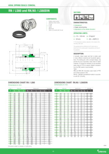
WAVE SPRING SEALS COMPONENTS: 1 Rotating contact surface 2 Stationary contact surface 3 O-rings 3a O-rings 4 Spring 5 Metal frame 5a Set screws 5b Ring CHARACTERISTICS: • Unbalanced. • System attached to the shaft by allen screws. • Not dependent on the rotation direction. OPERATING LIMITS: d,= 14 - 150 mm p= 10 kg/cm! v= 20 m/s t= -15- +200°C (*) (*) The temperature resistance depends on the material of the secondary seals used. The operating limits are defined by the PV factor which is determined for the sealing system characteristics and those of the application. DESCRIPTION: Recommended for working with sticky fluids and fluids laden with particles and fibres. Unlike the multispring models, the wave spring model cannot be blocked or obstructed and its open leaf design produces a self-cleaning effect. Standard L9 type stationary part. Seal compliant with standard EN 12756 (KU). Available with a pumping ring on the casing to reduce the temperature between the contact surfaces and facilitate the barrier fluid movement in the case of double mounting (reference LWS10-F). Contact surface kits supplied available. DIMENSIONS CHART Dimensions in mm Shaft Rotary part Stationary part Total length Shaft Rotary part Stationary part Total length * Multispring design manufacture for d1>100 mm. Dimensions subject to changes or modifications. SAFE INDUSTRY
カタログの1ページ目を開く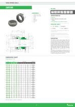
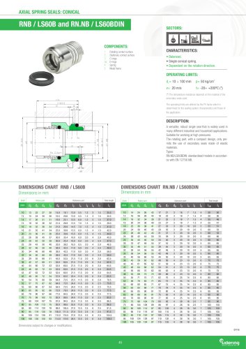
WAVE SPRING SEALS LWS10B SECTORS: COMPONENTS: 1 Rotating contact surface 2 Stationary contact surface 3 O-rings 3a O-rings 4 Spring 5 Metal frame 5a Set screws 5b Ring CHARACTERISTICS: • Balanced. • System attached to the shaft by alien screws. • Not dependent on the rotation direction. OPERATING LIMITS: d,= 14 - 100 mm p= 25 kg/cm! v= 20 m/s t= -50- +220°C (*) (*) The temperature resistance depends on the material of the secondary seals used. The operating limits are defined by the PV factor which is determined for the sealing system characteristics and those of the application....
カタログの2ページ目を開く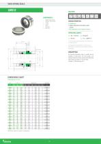
WAVE SPRING SEALS COMPONENTS: 1 Rotating contact surface 2 Stationary contact surface 3 O-rings 3a O-rings 4 Spring 5 Set screws 5a Metal frame CHARACTERISTICS: • Unbalanced. • System attached to the shaft by alien screws. • Not dependent on the rotation direction. OPERATING LIMITS: d1=20 - 100 mm p= 10 kg/cm! v= 20 m/s t= -15- +200°C (*) (*) The temperature resistance depends on the material of the secondary seals used. The operating limits are defined by the PV factor which is determined for the sealing system characteristics and those of the application. DESCRIPTION: Its mounting...
カタログの3ページ目を開く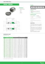
WAVE SPRING SEALS CHARACTERISTICS: • Balanced. • System attached to the shaft by alien screws. • Not dependent on the rotation direction. OPERATING LIMITS: d,= 18 - 100 mm p= 35 kg/cm! v= 20 m/s t= -15- +200°C (*) (*) The temperature resistance depends on the material of the secondary seals used. The operating limits are defined by the PV factor which is determined for the sealing system characteristics and those of the application. DESCRIPTION: The wave spring is protected from the fluid. Ideal for using in cleaning processes since the possibility of particles adhering to the seal is...
カタログの4ページ目を開く
WAVE SPRING SEALS Rotating contact surface Stationary contact surface O-rings O-rings Elastomeric cup Elastomeric cup Springs Metal frame CHARACTERISTICS: • Balanced. • Shaft fixing system WITHOUT screws. • Sentido rotación independiente. OPERATING LIMITS: d1= 20 ÷ 35 mm p= 35 kg/cm² v= 20 m/ (*) The temperature resistance depends on the material of the secondary seals used. The operating limits are defined by the PV factor which is determined for the sealing system characteristics and those of the application. DESCRIPTION: A wave spring mechanical seal in which the spring is isolated and...
カタログの5ページ目を開く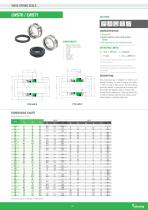
WAVE SPRING SEALS CHARACTERISTICS: COMPONENTS: 1 Rotating contact surface 2 Stationary contact surface 3 O-rings 3a O-rings 4 Spring 5 Metal frame 5a Set screws 5b Coupling pin • Unbalanced. • System attached to the shaft by Allen screws. • Not dependent on the rotation direction. OPERATING LIMITS: d1= 15.8 - 100 mm p= 10 kg/cm! v= 15 m/s t= -15- +200°C (*) (*) The temperature resistance depends on the material of the secondary seals used. The operating limits are defined by the PV factor which is determined for the sealing system characteristics and those of the application....
カタログの6ページ目を開くLIDERINGのすべてのカタログと技術パンフレット
-
 Paper Industry
4 ページ
-
 Dairy Industry
2 ページ
-
 Brewing Industry
2 ページ
-
 BRAIDED PACKING
8 ページ
-
 PACKING GLOSTER-PACK
8 ページ
-
 AUXILIARY PRODUCTS
3 ページ
-
 RMS MECHANICAL SEAL
7 ページ
-
 SEAT SHAPE
3 ページ
-
 BELLOW
18 ページ
-
 AXIAL/CONICAL SPRING
9 ページ
-
 MULTI-SPRING
12 ページ
-
 CARTRIDGES
84 ページ
-
 LS40C
LS40C1 ページ
-
 FH-FHC FN/LS15
1 ページ
-
 Lsc39-FQ
1 ページ
-
 RESERVOOIR LTS
1 ページ
-
 LMS11
LMS111 ページ
-
 LS
LS1 ページ
-
 LST-LHP
1 ページ
-
 LC-LQT
1 ページ
-
 LDC40
LDC401 ページ
-
 LDC21
LDC211 ページ
-
 LDC22-F
1 ページ
-
 LDC39-D
1 ページ
-
 LDC38
LDC381 ページ
-
 LDC80
LDC801 ページ
-
 Kitting
1 ページ
-
 LSC40-F
1 ページ
-
 LSC211A
1 ページ
-
 LSC211
1 ページ
-
 LSC21
LSC211 ページ
-
 LSC22
LSC221 ページ
-
 LSC39-F
1 ページ
-
 LSC39 FQ
1 ページ
-
 LSC38
LSC381 ページ
-
 LSC50-F
1 ページ
-
 Flat gaskets
12 ページ
-
 Lidering a new image
16 ページ