カタログの抜粋
DS-OLS2-FPD Digital Stepper Drive Technical Manual Technical Manual DS-OLS2-FPD Digital Stepping Driver
カタログの1ページ目を開く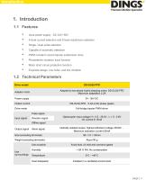
Input power supply : DC 24V~36V 8 level current selection and 8 level subdivision selection Single / dual pulse selection Capable of automatic detection PWM constant current bipolar subdivision drive Photoelectric isolation input function Motor short circuit protection function Exquisite design, low noise, and low vibration 1.2 Technical Parameters Drive model Adapter motor Adapted to two-phase hybrid stepping motor, DS-OLS2-FPD Maximum adaptation 2.2A Power supply Output current Drive mode Full-bridge bipolar PWM driver Pulse signal Input signal Direction signal Optocoupler input voltage H...
カタログの3ページ目を開く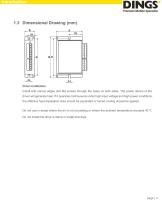
Drive installation Install with narrow edges and M4 screws through the holes on both sides. The power device of the driver will generate heat. If it operates continuously under high input voltage and high power conditions, the effective heat dissipation area should be expanded or forced cooling should be applied. Do not use in areas where the air is not circulating or where the ambient temperature exceeds 40 ℃ Do not install the drive in damp or metal shavings.
カタログの4ページ目を開く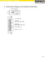
Schematic Diagram and Interface 2. Schematic Diagram and Interface Definition
カタログの5ページ目を開く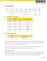
Current setting Subdivision setting Operating Mode Self test 3.1 Subdivision Setting DIP switch Pulse count / Revolution Operation mode Double pulse Pulse+Direction Mode : Pulse is added to the pulse input end. When the optocoupler at the direction input end is not connected, the motor rotates in one direction, and when the optocoupler at the direction input end is connected, the motor rotates in the other direction Dual Pulse Mode : When the pulse input terminal is pulsed, the motor rotates in one direction, and when the direction input terminal is pulsed, the motor rotates in the other...
カタログの6ページ目を開く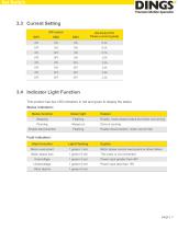
3.3 Current Setting DIP switch SW1 DS-OLS2-FPD Phase current (peak) 3.4 Indicator Light Function This product has two LED indicators in red and green to display the status: Status indication: Status function Green light Enable disconnection Explain Enable, motor phase locked but motor not running Drive is running Enable disconnection, motor can be free Fault indication: Alarm function Light Flashing Motor overcurrent Motor phase current overcurrent or driver failure Motor phase loss Power input greater than 40V Power input less than 15V Other alarms
カタログの7ページ目を開く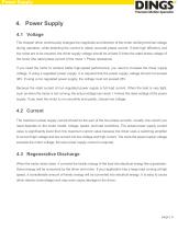
Power Supply 4. Power Supply 4.1 Voltage The chopper driver continuously changes the magnitude and direction of the motor winding terminal voltage during operation, while detecting the current to obtain accurate phase current. If both high efficiency and low noise are to be ensured, the driver supply voltage should be at least 5 times the rated phase voltage of the motor (the rated phase current of the motor × Phase resistance). If you need the motor to achieve better high-speed performance, you need to increase the driver supply voltage. If using a regulated power supply, it is required...
カタログの8ページ目を開く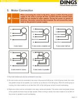
Motor Connection When connecting the motor to the drive, please confirm that the power supply to the drive is turned off first. Confirm that the unused motor Caution leads are not shorted to other objects. During the power on period of the driver, the motor cannot be disconnected. Do not connect the motor leads to the ground or power supply. 1) Four-wire motors can only be connected in one way. 2) Six-wire motors can be connected in two ways: full group and half group. In the full group mode, the motor has greater torque at low speeds, but it cannot run as fast as in the half group. When...
カタログの9ページ目を開く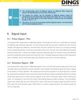
Motor Connection / Signal Input 1) The corresponding colors of different motors are different. When using the motors, the specifications of the motors shall prevail. 2) The phases are relative, but the windings of different phases cannot be connected to the terminals of the same phase of the driver (A +, A- is one phase, B +, B- is the other phase). If the motor direction is different from the expected direction, only A + , A-. 3) This driver can only drive two-phase hybrid stepping motors, not three-phase and five-phase stepping motors. 6. Signal Input 6.1 Pulse Signal : PUL Can accept...
カタログの10ページ目を開く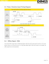
Signal Input 6.3 Pulse / Direction Input Timing Diagram Input signal waveform and timing (single pulse method) Input signal waveform and timing (double pulse method) PUL Input port (Forword rotation) DIR Input port (Reverse) Can accept 5VDC single ended or differential signals. When the built-in optocoupler is turned on, the motor phase current is cut off and the rotor is in a free state (offline state). When this function is not needed, the offline signal end can be suspended.
カタログの11ページ目を開く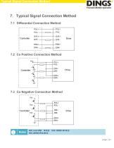
Typical Signal Connection Method 7. Typical Signal Connection Method 7.1 Differential Connection Method 7.2 Co Positive Connection Method Vcc 7.3 Co Negative Connection Method Vcc
カタログの12ページ目を開く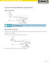
Typical Signal Connection Method Typical Connection Method for Signal Output Relay Connection When the relay is connected, it is required to connect diodes at both ends of the relay (such as IN4000 series) Optocoupler Connection The alarm output is photoelectric isolation, with a maximum withstand voltage of 30VDC and a maximum saturation current of 50mA. When the driver is working properly, the output is closed. When the driver makes an error, the output is suspended.
カタログの13ページ目を開く
Wiring Requirements In order to prevent the driver from being disturbed, it is recommended to use shielded cable for the control signal, and the shield layer should be shorted to the ground. Except for special requirements, the shielded wire of the control signal cable is grounded at one end: the upper end of the shielded cable is grounded The driver end of the wire is left floating. Grounding can only be performed at the same point in the same machine. If it is not a real ground wire, the interference may be serious, and the shielding layer is not connected at this time. Pulse and...
カタログの14ページ目を開く
International Customer Person in Charge : Daniel Jang daniel@dingsmotion.com No. 2850 Luheng Road, Changzhou Economic Development Zone, Jiangsu Province, China +86-519-85177825, 85177826 North America Customer Person in Charge : Nicolas Ha sales@dingsmotionusa.com 335 Cochrane Circle Morgan Hill, CA 95037 +1-408-612-4970 China Customer Person in Charge : +86-0519-8517 7807 No. 2850 Luheng Road, Changzhou Economic Development Zone, Jiangsu Province, China www.dingsmotion.com Sweet Shi info@dingsmotion.com No. 2850 Luheng Road, Changzhou Economic Development Zone, Jiangsu Province, China...
カタログの15ページ目を開くJiangsu DINGS' Intelligent Control Technology Co.のすべてのカタログと技術パンフレット
-
 General Catalog
295 ページ
-
 Simple Brochure
36 ページ