カタログの抜粋

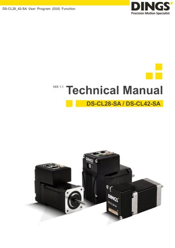
DS-CL28_42-SA Text Technical Manual
カタログの1ページ目を開く
Safety Pre-caution and Note on Installation...…………………..………….….…………..4 1.1 External Name and Function Setting of DS-CL28/42-SA Series
カタログの2ページ目を開く
Stopping Continuous Operation of Position Table………………………25 Communication Interface Circuit
カタログの3ページ目を開く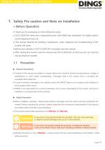
Safety Pre-caution and Note on Installation 1. Safety Pre-caution and Note on Installation ※ Before Operation ● Thank you for purchasing our DS-CL28/42-SA series. ● DS-CL28/42-SA series are a high-performance 32bit ARM chip embedded Full Digital position control stepping driving unit. ● This manual describe the handling, maintenance, repair, diagnosis and troubleshooting of DSCL28/42-SA series. ● Before start operation of DS-CL28/42-SA, thoroughly read this manual. ● After reading this manual, keep the manual near DS-CL28/42-SA, so that any user can read this manual whenever needed. General...
カタログの4ページ目を開く
Safety Pre-caution and Note on Installation Check the Product is damaged or parts are missing. Otherwise, the machine may get damaged or the user may get injured. Please carry the DS-CL28/42-SA carefully. Otherwise, the product may get damaged or user’s foot may get injured by dropping the product. Use non-flammable materials such as metal in the place where the DSCL28/42-SA is to be installed. Otherwise, a fire may occur. When installing several DS-CL28/42-SA in to be sealed place, install a cooling fan to keep the ambient temperature of the product as 50℃ or lower. Otherwise, a fire or...
カタログの5ページ目を開く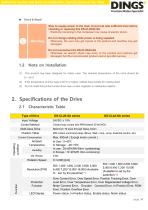
Safety Pre-caution and Note on Installation / Specifications of the Drive Check & Repair Stop to supply power to the main circuit and wait sufficient time before checking or repairing this DS-CL28/42-SA Electricity remaining in the condenser may cause of electric shock. Do not change cabling while power is being supplied. Otherwise, the user may get injured or the product and machine may get damaged. Do not reconstruct the DS-CL28/42-SA Otherwise, an electric shock may occur or the product and machine get damaged. And the reconstructed product cannot get after service. Note on Installation...
カタログの6ページ目を開く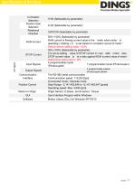
In-Position Selection Position Gain Selection Rotational Direction RUN Current STOP Current 0~63 (Selectable by parameter) 0~63 (Selectable by parameter) CW/CCW (Selectable by parameter) 50%~150% (Selectable by parameter) RUN current is flowing current value in the motor when motor is operating ( rotating ), It is set based on constant current of motor * Default factory setting value : 100% 20%~100% (Selectable by parameter) It is set as setting value of STOP current 0.1 sec after motor stop. STOP current value is at a ratio against RUN current value of motor * Default factory setting value...
カタログの7ページ目を開く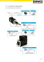
Controller Configuration
カタログの8ページ目を開く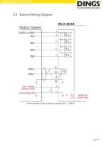
External Wiring Diagram
カタログの9ページ目を開く
External Name and Function Setting of DS-CL28/42-SA 2.4 External Wiring Diagram Power, Communication, I/O Connector
カタログの11ページ目を開く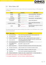
In case of DS-CL28/42-SA product, status of LED can be checked by turning on / off the status LED and flashing Status Disable Enable Enable & Communication In Operation In-position deviation Alarm Function Green : — — — — Red : Green : ——————— Red : Greed : ——————— Red : • • Greed : ——————— Red : ——————— Green : • • • • • • Red : • • • • • • Green : Red : — — — — LED status Green light flashing , Red light off Green light On , Red light off Green light On , Red light flashing Green & Red lights On Green & Red lights alternately flashing Red light flashing repeat as many as alarm numbers The...
カタログの12ページ目を開く
The Network ID of DS-CL42-SA can be set using the Ezi-MOTION Plus-R GUI. The setting method is as follows. Connect the communication line to the product and input the power. Execute the Ezi-MOTION Plus-R program (version 6.40.12.18 or later). Select the port number of the computer connected to the product and set the communication speed to 115,200 [bps]. Press the "Connect" button and wait for a while, the currently connected product is displayed in the Board List window. When right-click on the product which you want to modify, the menu appears. Then select to "Config Slave ID"...
カタログの13ページ目を開く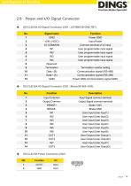
Power and I/O Signal Connector DS-CL28-SA I/O Signal Connector (CN1 : JST/BM12B-GHS-TBT) No. Signal name Input Power Common terminal of IO input User programmable input signal User programmable input signal User programmable input signal User programmable input signal Termination resistor setting Power GND (Communication signal GND) Input Common Input Signal common terminal Output Common Output Signal common terminal User Input (User Input1) User Input (User Input2) User Input (User Input3) User Input (User Input4) User Input (User Input5) User Input (User Input6) User Output (User Output1)...
カタログの14ページ目を開く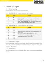
Signal Cabling All control I/O signals use connector CN1 as specified below Signal name programmable input = total 4 input pins Function Origin sensor signal, Positive Limit sensor signal Negative Limit sensor signal User input 0 ~ User input 8 (User IN 0 ~ User IN 8) Clear Pos, Soft Stop(Stop), Jog+, Jog-, Alarm Reset, Servo ON Origin Search, Emergency Stop(E-Stop) programmable input = total 7 input pins Function Origin sensor signal, Positive Limit sensor signal Negative Limit sensor signal User input 0 ~ User input 8 (User IN 0 ~ User IN 8) Clear Pos, Soft Stop(Stop), Jog+, Jog-, Alarm...
カタログの15ページ目を開く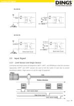
Input Signal 3.3.1 Limit Sensor and Origin Sensor Limit sensor and origin sensor are assigned to LIMIT+, LIMIT- , and ORIGIN pin in the CN1 connector respectively. LIMIT+ and LIMIT- sensors are used to limit the motion of each axis to prevent mechanical collision. Origin sensor is to set the origin of equipment
カタログの16ページ目を開くJiangsu DINGS' Intelligent Control Technology Co.のすべてのカタログと技術パンフレット
-
 General Catalog
295 ページ
-
 Simple Brochure
36 ページ