
カタログの抜粋

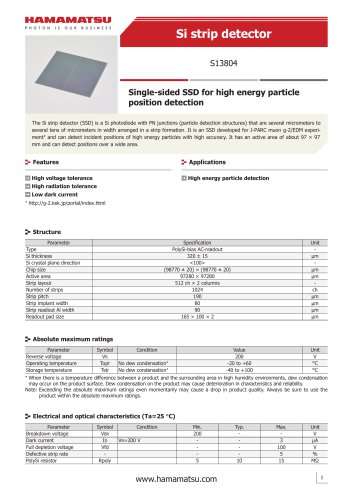
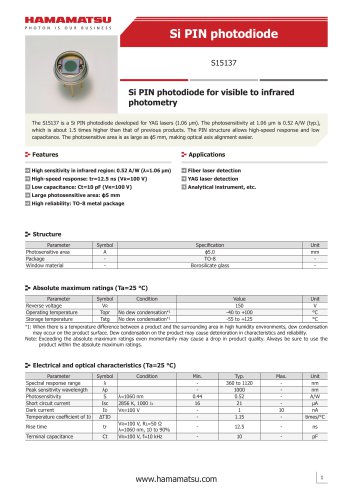
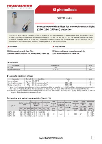
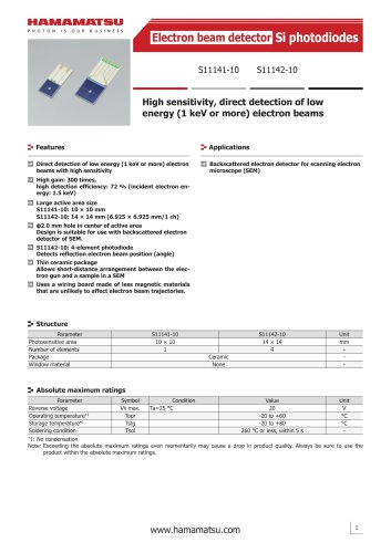
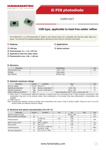
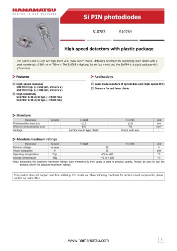
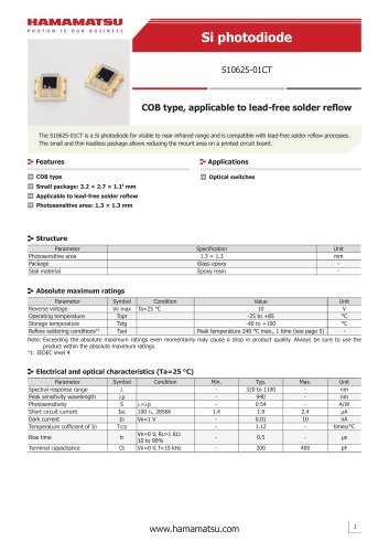
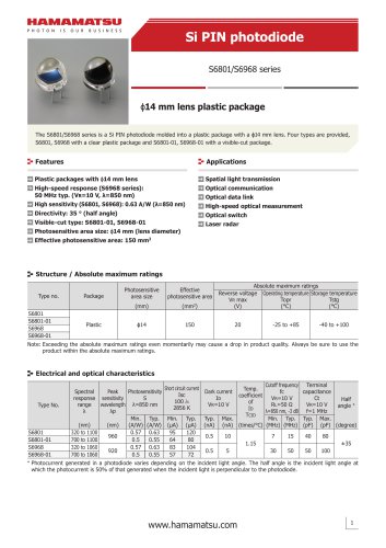
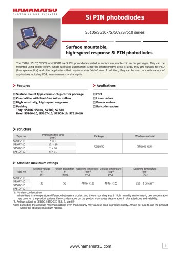
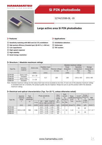
Distance linear image sensor S15452-01WT NIR-enhanced type, measures the distance to an object by TOF method The distance image sensor is designed to measure the distance to an object by TOF (time-of-flight) method. When used in combination with a pulse modulated light source, this sensor outputs phase difference information on the timing that the light is emitted and received. Distance data can be obtained by performing calculation on the output signal with an external signal processing circuit or on a PC. We provide an evaluation kit for this product. Contact us for detailed information. High sensitivity in the near infrared region Obstacle detection (self-driving, robots, etc.) Improved tolerance to background light Security (intrusion detection, etc.) Compact wafer level package (WLP) type Shape recognition (logistics, robots, etc.) Motion capture Touchless operation Structure Parameter Image size Pixel pitch Pixel height Number of pixels Number of effective pixels Package Note: This product is not hermetically sealed. Unit mm μm μm pixels pixels - Absolute maximum ratings Parameter Symbol Analog supply voltage Vdd(A) Digital supply voltage Vdd(D) Pixel amplifier Vsf Analog input Pixel reset Vr terminal voltage Photosensitive area Vpg Pixel reset pulse pix_reset Signal sampling pulse phis Digital input Master clock pulse mclk terminal voltage Signal readout trigger pulse trig Output signal sync pulse dclk Charge transfer clock pulse voltage VTX1, VTX2, VTX3 Operating temperature Topr Storage temperature Tstg Soldering temperature*2 Tsol *1: When there is a temperature difference between a product and the surrounding area in high humidity environment, dew condensation may occur on the product surface. Dew condensation on the product may cause deterioration in characteristics and reliability. *2: Reflow soldering, IPC/JEDEC J-STD-020 MSL 2, see P.9 Note: Exceeding the absolute maximum ratings even momentarily may cause a drop in product quality. Always be sure to use the product within the absolute maximum ratings.
カタログの1ページ目を開く
Distance linear image sensor Recommended terminal voltage (Ta=25 °C) Parameter Analog supply voltage Digital supply voltage Pixel amplifier Bias voltage Pixel reset Photosensitive area High level Pixel reset pulse voltage Low level High level Signal sampling pulse voltage Low level High level Master clock pulse voltage Low level High level Signal readout trigger pulse voltage Low level Output signal sync pulse High level voltage Low level Symbol Vdd(A) Vdd(D) Vsf Vr Vpg pix_reset phis mclk trig dclk Min. 3.2 3.2 2.5 0.6 Vdd(D) × Vdd(D) × Vdd(D) × Vdd(D) × Vdd(D) × - Max. 3.4 3.4 2.7 1.0...
カタログの2ページ目を開く
Distance linear image sensor Spectral response (typical example) (Ta=25 °C) Relative sensitivity Block diagram Vdd(A) GND(A) A1 B2 CLTX Photodiode array 80 pixels (Number of effective pixels: 64) CLTX CLTX Bias generator Sample-and-hold circuit C1 Vout2 Buffer amp mclk B4 trig C4 Horizontal shift register C3 Basic connection example Buffer amp Vout1
カタログの3ページ目を開く
Distance linear image sensor phis trig Output light Output light tf(phis) mclk tf(dclk) dclk td(dclk) tr(pix_reset) tf(trig) tf(Vout)
カタログの4ページ目を開く
Distance linear image sensor Calculation method of frame rate Frame rate=1/4 of subframe time If the integration time is longer than the readout time Time per subframe=Integration time × (Non-destructive readout count - 1) + Readout time If the integration time is shorter than the readout time Time per subframe=Readout time × Non-destructive readout time Note: The integration time setting needs to be changed depending on the required distance accuracy and usage environment factors such as background light. [Readout time calculation] Readout time= 1 × Number of horizontal pixels Clock pulse...
カタログの5ページ目を開く
Distance linear image sensor Parameter Symbol Master clock pulse duty ratio Master clock pulse rise and fall times*7 tr(mclk), tf(mclk) Pixel reset pulse high period thp(pix_reset) Pixel reset pulse rise and fall times*7 tr(pix_reset), tf(pix_reset) Signal sampling pulse high period thp(phis) Signal sampling pulse rise and fall times*7 tr(phis), tf(phis) Signal readout trigger pulse rise and fall times*7 tr(trig), tf(trig) Time from rising edge of master clock pulse to rising t0 edge of pixel reset pulse Time from falling edge of pixel reset pulse to rising edge t1 of signal sampling pulse...
カタログの6ページ目を開く
Distance linear image sensor Input terminal capacitance (Ta=25 °C, Vdd=3.3 V) Parameter Charge transfer clock pulse internal load capacitance Dimensional outline (unit: mm) Recommended land pattern (unit: mm) P0.36 × 5=1.8 1st pixel Direction of scan Photosensitive surface Tolerance unless otherwise noted: ±0.1 Au electrode * Distance from package center to photosensitive area center Symbol Vdd(A) Vout1 Vout2 Vpg GND(A) GND(D) Vsf dclk Vdd(D) NC mclk trig Vr pix_reset phis VTX3 VTX2 VTX1 Description Analog supply voltage Output signal 1 Output signal 2 Photosensitive area bias voltage...
カタログの7ページ目を開く
Distance linear image sensor Reel packing specifications Reel (conforms to JEITA ET-7200) Outer diameter ϕ180 mm Electrostatic characteristics Conductive Embossed tape (unit: mm, material: PS, conductive) Packing quantity 500 pcs/reel Packing state Reel and desiccant in moisture-proof packaging (vacuum-
カタログの8ページ目を開く
Distance linear image sensor Recommended soldering conditions 300 °C 245 °C max. ⸱ This product supports lead-free soldering. After unpacking, store it in an environment at a temperature of 30 °C or less and a humidity of 60% or less, and perform soldering within 1 year. ⸱ The effect that the product receives during reflow soldering varies depending on the circuit board and reflow oven that are used. When you set reflow soldering conditions, check that problems do not occur in the product by testing out the conditions in advance. ⸱ In order to improve reliability, we recommend that you use...
カタログの9ページ目を開く
Distance linear image sensor Evaluation kit for distance linear image sensor C15356 An evaluation kit [70 mm (H) × 55 mm (V)] is available for the S15452-01WT distance linear image sensor (with the S15452-01WT). Contact us for detailed information. Information described in this material is current as of October 2020. Product specifications are subject to change without prior notice due to improvements or other reasons. This document has been carefully prepared and the information contained is believed to be accurate. In rare cases, however, there may be inaccuracies such as text errors....
カタログの10ページ目を開くHAMAMATSUのすべてのカタログと技術パンフレット
-
 PHOTON COUTING HEAD
4 ページ
-
 FLAT PANEL TYPE
4 ページ
-
 SPAD MODULES
5 ページ
-
 LIGHTNINGCURE
29 ページ
-
 Xenon Flash Lamps
19 ページ
-
 ORCA-FUSION C14440-20UP
12 ページ
-
 NanoZommer series
8 ページ
-
 C13410 series
4 ページ
-
 C13410-06A
4 ページ
-
 PMA-12
8 ページ
-
 L12542
4 ページ
-
 FLAT EXCIMER
16 ページ
-
 Optical Gauge series
23 ページ
-
 L15208-01
3 ページ
-
 L15856-01
3 ページ
-
 L14001-01
2 ページ
-
 L11854-336-05
2 ページ
-
 L14351-02
4 ページ
-
 GC-113A
2 ページ
-
 IMAGEMX2 series
8 ページ
-
 ORCA-Fusion BT
9 ページ
-
 DIUTHAME
12 ページ
-
 J12853
2 ページ
-
 J12432-01
2 ページ
-
 J10919 SERIES
2 ページ
-
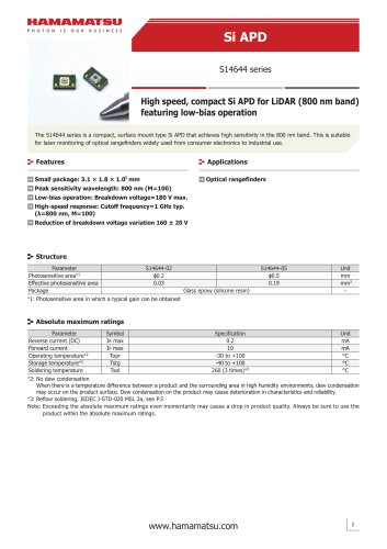 Si APD S14644 series
6 ページ
-
 C15780-401
4 ページ
-
 H15460-40
4 ページ
-
 R14755U-100
2 ページ
-
 Photo IC for rangefinder
14 ページ
-
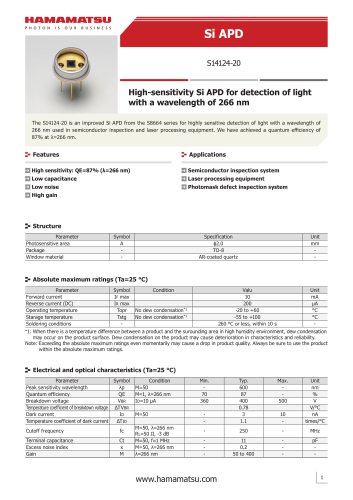 Si APD S14124-20
3 ページ
-
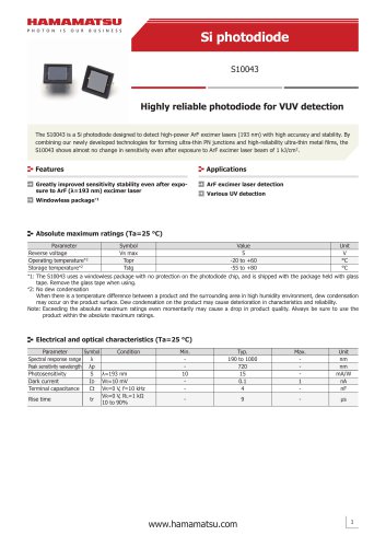 Si photodiode S10043
3 ページ
-
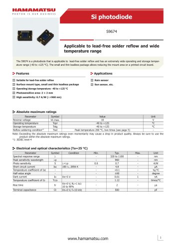 Si photodiode S9674
5 ページ
-
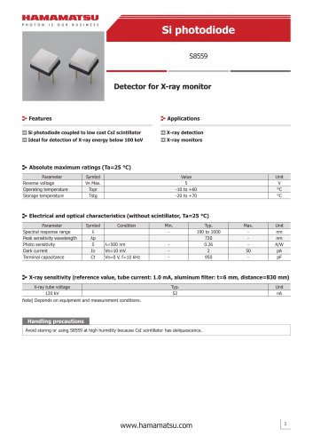 Si photodiode S8559
3 ページ
-
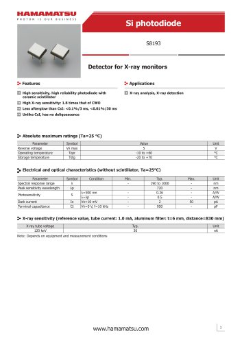 Si photodiode 8193
3 ページ
-
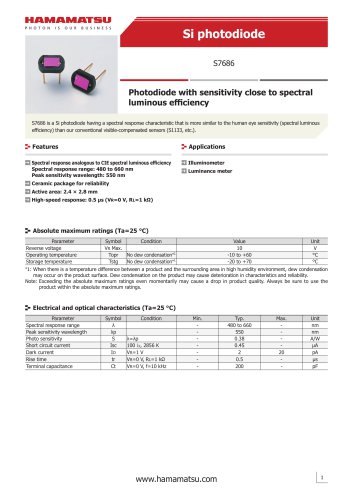 Si photodiode S7686
4 ページ
-
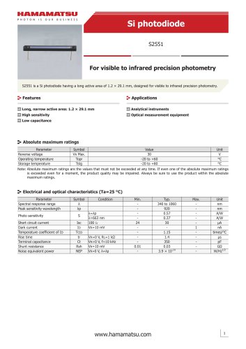 Si photodiode S2551
4 ページ
-
 C13398 series
5 ページ
-
 InGaAs Image sensors
17 ページ
-
 Si APD S14645 series
6 ページ
-
 Si APD S14643-02
6 ページ
-
 MEMS mirror S13124-01
10 ページ
-
 LIGHT SOURCES
23 ページ
-
 PHOTOTUBES
8 ページ
-
 FLAME SENSOR UVTRON
4 ページ
-
 PSD
PSD8 ページ
-
 InGaAs Photodiodes
20 ページ
-
 Infrared Detectors
36 ページ
-
 Photo IC
8 ページ
-
 Image Sensors
48 ページ
-
 Si Photodiodes
48 ページ
-
 Si APD
16 ページ
-
 MPPC®, MPPC modules
34 ページ
-
 Photonic Devices
44 ページ
-
 IMAGE INTENSIFIERS
20 ページ
-
 FLOW CELLS
4 ページ
-
 COMPACT HIGH VOLTAGE
2 ページ
-
 SCANBLOCK C10516
4 ページ
-
 UV TRONR DRIVING
2 ページ
-
 High sensitivity
2 ページ
-
 Si photodiodes
41 ページ


カタログアーカイブ
-
 Opto-semiconductor Catalog
38 ページ


