グループ: Gilbarco Veeder-Root

カタログの抜粋
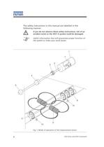
If you do not observe these safety instructions, risk of an accident exists or the VISY-X system could be damaged. Useful information that will guarantee proper function ofthe system or make your work easier. 3 4271 81096 5 10 > Fig. 1: Mode of operation of the measurement sensor 6 VISY-Stick and VISY-Command size="-3">
カタログの6ページ目を開く
For the installation and maintenance of the measurement sensor, the regulations in accordance with ElexV specifications and the German equipment safety law as well as the generally recognised rules and regulations of technology and these operating instructions are applicable.Also observe the local safety regulations and accidentprevention regulations not mentioned in this manual of operating instructions. > VISY-Stick and VISY-Command 7 >
カタログの7ページ目を開く
The measurement sensors are only allowed to be connected tomeasuring transducers that have been certified by a recognised European testing authority and the electrical data of which meet the following requirements:U > i 15VI > i 30mAP > i 0,1WYou can also connect several measurement sensors to themeasurement evaluation system.First of all, however, install the measurement sensors in thetanks by positioning the sensors centrally in the middle of tank to the extent possible. Height differences between the deepest point of the tank bottom and the end of the probe tube (= installation offset)...
カタログの8ページ目を開く
tank diameter a: deviation from the longitudinal axis [mm] > b: height difference tank bottom bottom end probe tube [mm] Fig. 2: measurement sensor > VISY-Stick and VISY-Command
カタログの9ページ目を開く
Tank muff 1 1/2 inches > During the assembly work, it is important make sure thatthe probe tube is not bent. If the tank muff intended to be used for the assembly work has an internal thread of at least 1 1/2 inches, the installation of the probe (see Fig. 3) must be carried out in the following steps. For internal threads that are larger than 1 1/2 inches, the corresponding reducer pieces must be used:Check firm fit of the retaining ring so that the floats cannotfall into the tank. > The floats must be pushed onto the probe tube with the marking facing upward so that the measurement can be...
カタログの10ページ目を開く
probe length measuring range product measuring range water >
カタログの11ページ目を開く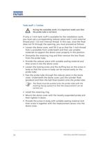
Tank muff = 1 inches > During the assembly work, it is important make sure thatthe probe tube is not bent. If only a 1-inch tank muff is available for the installation work, you must use a corresponding reducer piece with 1-inch external thread and 1 1/2-inch internal thread. In this case, since the float does not fit through the opening, you must proceed as follows:Loosen the dome cover, and lift it up so that the 1-inch threadhole is accessible from underneath and then use suitable materials to support the dome cover properly in this position.ՕDismantle the retaining ring and then remove...
カタログの12ページ目を開く
VISY-Stick replacement instructions In order to avoid redefining the fixed offset when fitting a newprobe you must reproduce the distance between the old probe and the floor of the tank as accurately as possible. The distance must be at least 5 mm before and after. To do this, before commencing dismantling work on the old probe mark the point where the probe tube emerges from the threaded joint using a suitable pen, as well as the position of the stuffing box on the screw body.Then undo the threaded joint (first undo the locking screw withan Allen key and then the stuffing box) and...
カタログの13ページ目を開く
Electrical connection For the wiring of each measurement sensor with themeasurement evaluation system, you will require a four-core unshielded cable which is connected in the probe head of the measurement sensor (see Fig.4). > + A B -Ger.-Nr. Fig. 4: cable connection measurement sensor The connections to be joined on the measurement evaluationsystem and on the measurement sensor identically labelled. > Observe the general installation regulations! Refer to the following table for information on the required line cross-sections. Cable lengthLine cross-section up to 200m4 x 1mm > 2 up to...
カタログの14ページ目を開く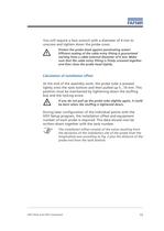
You will require a face wrench with a diameter of 4 mm tounscrew and tighten down the probe cover. > Protect the probe head against penetrating water! Efficient sealing of the cable entry fitting is guaranteed starting from a cable external diameter of 6 mm. Make sure that the cable entry fitting is firmly screwed together and then close the probe head tightly. Calculation of installation offset At the end of the assembly work, the probe tube is pressedlightly onto the tank bottom and then pulled up 5...10 mm. This position must be maintained by tightening down the stuffing box and the...
カタログの15ページ目を開く
Explosion protection:EEx ia IIC T6Permit:T֜V 99 ATEX 1391 orTV 99 ATEX 1496System of protection:IP 68Permissibleambient temperature:-25 C to 75 C in T4(probe head)-25 C to 65 C in T5-25 C to 50 C in T6Connection data:U > I 15 VP > I 0.1 WI > i 30 mAC > i < 10 nFL > i < 0.1 mHSpecial lengths:2,000 mm (for tank diameter 1,600 mm)2,400 mm (for tank diameter 2,000 mm) 2,900 mm (for tank diameter 2,500 mm) 3,300 mm (for tank diameter 2,900 mm)Probe head:ܘ 52 mm x 107 mmProduct float:cylinder 43 mm, height 40 mm Water float:ball ؘ 43 mm orcylinder 43 mm, height 20 mmConnection:screw-in body with...
カタログの16ページ目を開く
Service mode/S1 Serial RS232 interface for system configuration using the pro- gram VISY-Setup. For this operation, the switch S1 must be in the position OFF OFF. All other switch positions are intended to be used for future options, e.g. the software VISY-Quick. > Components of interface card VI-3 (see Fig. 5 and 6) > Status display Following a system switching-on operation or a reset of the interface card VI-3, the software version is indicated first. The software version is represented by three numbers displayed after one another on the screen, e.g. 2-0-1 corresponds to version 2.01....
カタログの17ページ目を開く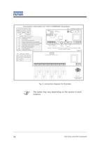
2: TxD3: RxD5: -RxD Host-TxD ח Expansion-TxD Host - Status of sensors ON12 -S1 > 12345678LNPE 1 - 89 - 16 HostExpansion Display:- Service Reset Tank > + AB - + AB - + AB - + AB - + AB - + AB - + AB - + AB - + AB - + AB - + AB - + AB - > sensorsensorsensor sensorsensorsensorsensor sensor 8 PENL + AB - + AB - + AB - + AB - >
カタログの18ページ目を開くFAFNIR GmbHのすべてのカタログと技術パンフレット
-
 TORRIX M12 MOBILE
2 ページ
-
 TORRIX XTS
2 ページ
-
 TORRIX 6
1 ページ
-
 LPG Sensors
8 ページ
-
 SEPARIX
8 ページ
-
 Process Automation
28 ページ
-
 O²-PID
4 ページ
-
 COMS Leaflet
4 ページ
-
 VAPORIX Flow and Control
40 ページ
-
 Wallmounting Typ 907
4 ページ
-
 QE 200
4 ページ
-
 UM 2.1/2.2/2.3
20 ページ
-
 TORRIX HART
28 ページ
-
 TORRIX RS485 Modbus
16 ページ
-
 TORRIX M12
40 ページ
-
 FAFNIR Hart Setup
9 ページ
-
 LS 300 / 500
7 ページ
-
 76 A / NB 220
5 ページ
-
 76 / NB 220
2 ページ
-
 SECON-X
4 ページ
-
 PRESSURIX
12 ページ
-
 Insite360
4 ページ
-
 Plugs
Plugs12 ページ
-
 UM 2.1/UM 2.2/UM 2.3
20 ページ
-
 TORRIX-HART
28 ページ
-
 DIVELIX
8 ページ
-
 CONDURIX-HART
28 ページ
-
 CONDURIX
24 ページ
-
 VAPORIX
12 ページ
-
 VISY-X
24 ページ
-
 Accessories
3 ページ
-
 VISY-Command Web
4 ページ
-
 VISY-Reed
4 ページ
-
 VISY-RF
2 ページ
-
 VISY-Stick
15 ページ
-
 VISY-TD Display
2 ページ
-
 VISY-View Touch
2 ページ
-
 TORRIX
10 ページ
-
 TORRIX CI
1 ページ
-
 TORRIX RS485
3 ページ
-
 UM-X Transducer
3 ページ
-
 TEMPERIX
8 ページ
-
 VISY-Command
5 ページ
-
 LPG-Sensoren
8 ページ


カタログアーカイブ
-
 2019 VISY-Stick Flex
2 ページ
-
 2016 VISY-Stick Flex
2 ページ
-
 HPH Ex d
3 ページ
-
 VISY-Monitor
2 ページ
-
 VISY-X LON
10 ページ
-
 SEPARIX
23 ページ
-
 VAPORIX Flow/Control
32 ページ
-
 VISY-Setup V 3.1.0
40 ページ
-
 VISY-Setup V2.10
42 ページ
-
 VISY-View
24 ページ


