グループ: Gilbarco Veeder-Root

カタログの抜粋

Technical Documentation
カタログの1ページ目を開く
© Copyright: Reproduction and translation are permitted only with the written consent of the FAFNIR GmbH. The FAFNIR GmbH reserves the right to make product alterations without prior notice. Table of c
カタログの3ページ目を開く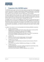
Properties of the VAPORIX system The VAPORIX system (vapor recovery information system) is an automatic monitoring device to check the function of the vapor recovery systems (Stage II) at filling stations. The VAPORIX system is approved in compliance with the German 21th Federal Immission Control Ordinance (BImSchV) and the European Directives 2009/126/EC and 2014/99/EU. During the fuelling process the vapour flow is registered together with the fuel flow of the according fuelling point. The fuel flow data is taken over from the pulse outputs of the dispenser computer. After the fuelling...
カタログの4ページ目を開く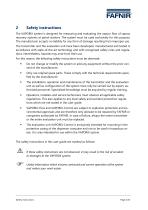
Safety instructions The VAPORIX system is designed for measuring and evaluating the vapour flow of vapour recovery systems at petrol stations. The system must be used exclusively for this purpose. The manufacturer accepts no liability for any form of damage resulting from improper use. The transmitter and the evaluation unit have been developed, manufactured and tested in accordance with state-of-the-art technology and with recognised safety rules and regulations. Nevertheless, hazards may arise from their use. For this reason, the following safety instructions must be observed: Do not...
カタログの5ページ目を開く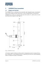
VAPORIX-Flow transmitter Design and function The VAPORIX-Flow is a calorimetric flow transmitter with integrated vapour concentration sensor, which supplies accurate results even in case of changing vapour concentrations. VAPORIX-Flow consists of a measuring tube with inlet section (1), outlet section (2) and side-fitted sensor support (3) (see Figure 1). Figure 1: VAPORIX-Flow sensor In the sensor support (3) there are three sensors. A temperature sensor to measure the vapour temperature, a heat dissipating sensor to determine the flow and a heat dissipating sensor to measure the vapour...
カタログの6ページ目を開く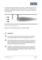
The measurement of flow rate and vapour concentration is based on the calorimetric principle. Here, the heat dissipation of the electrically heated sensor into the flowing medium is utilized as a measuring effect. The vapour concentration is required for precise evaluation of the flow rate. Figure 2: Function principle of the VAPORIX-Flow The grey tail represents the heat dissipation into the flowing medium. Installation When working with the transmitters, the national safety and accident prevention regulations and safety instructions in this manual must be observed. When installing and...
カタログの7ページ目を開く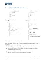
Installation of VAPORIX-Flow in the dispenser from the dispensing hose from the dispensing hose Inlet section Inlet section Pulsation damper Pulsation damper Frequency converter to the vapour recovery collecting pipe Proportional valve to the vapour recovery collecting pipe Figure 3: Examples - Installation positions of VAPORIX-Flow When installing the VAPORIX-Flow the following installation conditions must be fulfilled (see Figure 3): The installation of the VAPORIX-Flow is done in the vapour recovery pipe upstream of the pump and any existing control valve. The mounting position is...
カタログの8ページ目を開く
• In front of the transmitter a straight vapour pipe (inlet section), smooth or corrugated, is required with a length of minimum 50 mm and an inner diameter of 8 ... 12 mm. • The inflow into the inlet section may be done with a minimum radius of 50 mm. • The inlet section can be connected using a standard fitting. • The connection to the outlet section of the transmitter can be done in any form. The direct mounting of a 90° degree fitting is also permitted. • The casing of the VAPORIX-Flow is to be attached vertically in the dispenser with the help of clamps. Different...
カタログの9ページ目を開く
Measures in case of pulsation Due to the pumping process, most vapour recovery pumps in vapour recovery systems produce pressure surges which result in a pulsating flow behaviour. This pulsation is very prominent in piston and diaphragm pumps. With dual-piston pumps, these effects are much smaller than with single-cylinder piston or single-cylinder diaphragm pumps. With vane pumps, the pulsation is usually negligible. Within the pipeline system, the pressure surges result in reflections and thus can cause resonances. The accuracy of the VAPORIX system is affected by the pulsation. The...
カタログの10ページ目を開く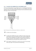
Connection of the VAPORIX-Flow to the VAPORIX-Control The 8-core connecting cable (4 m long, Ø approx. 6 mm) is an integral part of the transmitter. To pull the cable through suitable cable glands up to the installation point of the VAPORIX-Control in the head of the dispenser, the plug must be disconnected first and then fitted again as shown in the figure below. Figure 4: Pin assignment of the connecting cable for VAPORIX-Flow - VAPORIX-Control The cable must not be shortened. The cable of the VAPORIX-Flow, which is installed in the vapour recovery pipe of the dispenser with the lower...
カタログの11ページ目を開く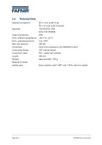
Explosion protection: Approval: Index of protection Perm. ambient temperature: Perm. operating pressure: Max. test pressure: Connection: Connecting thread: Connection cable: Length: Weight: Material of media wetted parts: ©II 1 G Exia MB T4 Ga ©II 1/2 G Ex ia IIB T4 Ga/Gb TOV 99 ATEX 1509, lECEx TUN 08.0008 IP68 -40 °C to +65 °C max. ATM 300 kPa Only to the evaluation unit VAPORIX-Control 3/8" internal thread PVC - partly fuel resistant 269 mm approximately 1100 g Brass, stainless steel 1.4401 and 1.4436, steel zinc plated Page 9/35 VAPORIX-Flow transmitter
カタログの12ページ目を開く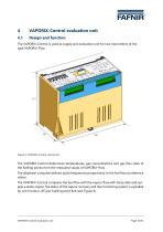
VAPORIX-Control evaluation unit Design and function The VAPORIX-Control is used as supply and evaluation unit for two transmitters of the type VAPORIX-Flow. Figure 5: VAPORIX-Control central unit The VAPORIX-Control determines temperatures, gas concentrations and gas flow rates of the fuelling points from the measured values of VAPORIX-Flow. The dispenser computer delivers pulse frequencies proportional to the fuel flow as reference values. The VAPORIX-Control compares the fuel flow with the vapour flow with these data and outputs a status signal. The status of the vapour recovery and the...
カタログの13ページ目を開くFAFNIR GmbHのすべてのカタログと技術パンフレット
-
 TORRIX M12 MOBILE
2 ページ
-
 TORRIX XTS
2 ページ
-
 TORRIX 6
1 ページ
-
 LPG Sensors
8 ページ
-
 SEPARIX
8 ページ
-
 Process Automation
28 ページ
-
 O²-PID
4 ページ
-
 COMS Leaflet
4 ページ
-
 Wallmounting Typ 907
4 ページ
-
 QE 200
4 ページ
-
 UM 2.1/2.2/2.3
20 ページ
-
 TORRIX HART
28 ページ
-
 TORRIX RS485 Modbus
16 ページ
-
 TORRIX M12
40 ページ
-
 FAFNIR Hart Setup
9 ページ
-
 LS 300 / 500
7 ページ
-
 76 A / NB 220
5 ページ
-
 76 / NB 220
2 ページ
-
 SECON-X
4 ページ
-
 PRESSURIX
12 ページ
-
 Insite360
4 ページ
-
 Plugs
Plugs12 ページ
-
 UM 2.1/UM 2.2/UM 2.3
20 ページ
-
 TORRIX-HART
28 ページ
-
 DIVELIX
8 ページ
-
 CONDURIX-HART
28 ページ
-
 CONDURIX
24 ページ
-
 VAPORIX
12 ページ
-
 VISY-X
24 ページ
-
 Accessories
3 ページ
-
 VISY-Command Web
4 ページ
-
 VISY-Reed
4 ページ
-
 VISY-RF
2 ページ
-
 VISY-Stick
15 ページ
-
 VISY-TD Display
2 ページ
-
 VISY-View Touch
2 ページ
-
 TORRIX
10 ページ
-
 TORRIX CI
1 ページ
-
 TORRIX RS485
3 ページ
-
 UM-X Transducer
3 ページ
-
 TEMPERIX
8 ページ
-
 VISY-Command
5 ページ
-
 LPG-Sensoren
8 ページ


カタログアーカイブ
-
 2019 VISY-Stick Flex
2 ページ
-
 2016 VISY-Stick Flex
2 ページ
-
 HPH Ex d
3 ページ
-
 VISY-Monitor
2 ページ
-
 VISY-X LON
10 ページ
-
 SEPARIX
23 ページ
-
 VAPORIX Flow/Control
32 ページ
-
 VISY-Setup V 3.1.0
40 ページ
-
 VISY-Setup V2.10
42 ページ
-
 VISY-View
24 ページ