グループ: Gilbarco Veeder-Root

カタログの抜粋
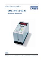
Technical Documentation UM 2.1/UM 2.2/UM 2.3 Measurement evaluation units
カタログの1ページ目を開く
© Copyright: Reproduction and translation only with the written consent of the company FAFNIR. FAFNIR reserves the right to carry out product alterations without prior notice. Measurement evaluation units UM 2.1/UM 2.2/UM 2.3
カタログの2ページ目を開く
Measurement evaluation units UM 2.1/UM 2.2/UM 2.3
カタログの3ページ目を開く
Characteristic features of the measurement evaluation units UM 2.1, UM 2.2 and UM 2.3 The measurement evaluation units UM 2.1, UM 2.2 and UM 2.3 U / UM 2.3 I are used for evaluating and displaying levels of liquids in tanks. The levels measured and transferred to the measurement evaluation units are processed in such a way that they can either be read off a display on the measurement evaluation units or have an electrical output: • UM 2.1 indicates the level in the form of a bar display and outputs two freely definable limit values via changeover contacts. • UM 2.2 provides an output of...
カタログの4ページ目を開く
The measurement evaluation units UM 2.1, UM 2.2, UM 2.3 U, or UM2.3 l serve the purpose of measuring and evaluating the filling levels in tanks. Use the system for this purpose only. The manufacturer shall not be liable for any form of damage resulting from improper use! The measurement evaluation units were developed, manufactured and inspected in accordance with state-of-the-art technology and with recognised technical safety rules and regulations. Nevertheless, hazards may arise from the use of these devices. Therefore, observe the following safety instructions. Do not change or modify...
カタログの5ページ目を開く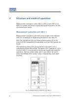
Structure and mode of operation Measurement evaluation units UM 2.1, UM 2.2 and UM 2.3 U/ UM 2.3 I contain the power supply and signal evaluation for the connected level sensor. Measurement evaluation unit UM 2.1 Measurement evaluation unit UM 2.1 has a light-strip indicator with 5% increments for displaying the levels in the tank (1). With the Test button (4) and three potentiometers (5) at the bottom of the measurement evaluation unit two limit values can be set. The operating state of the measurement evaluation unit is indicated by three LEDs (LEDs). The green LED „Operation“ (3) is lit...
カタログの6ページ目を開く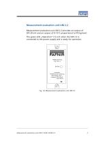
Measurement evaluation unit UM 2.2 Measurement evaluation unit UM 2.2 provides an output of 0/4–20 mA and an output of 0–10 V proportional to filling level. The green LED „Operation“ (1) is lit when the UM 2.2 is connected to the power supply and is ready for operation. 1 Hersteller: FAFNIR GmbH Hamburg Hilfsenergie: 230 V Ausgang: 0(4)–20mA max. 500 Ω Fig. 1b: Measurement evaluation unit UM 2.2 Measurement evaluation units UM 2.1/UM 2.2
カタログの7ページ目を開く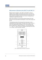
Measurement evaluation units UM 2.3 U and UM 2.3 I Measurement evaluation units UM 2.3 and UM 2.3 I have a 4-digit numeric display for indication the levels in the tank (1). With the aid of the plus (2) and ok buttons (7) at the top of the measurement evaluation unit the unit can be configured and matched to respective tank data. With the Test button (5) and three potentiometers (6) at the bottom of the measurement evaluation unit two limit values can be set. The operating state of the measurement evaluation unit is indicated by three LEDs (LEDs). The green LED „Power“ (4) is lit when the...
カタログの8ページ目を開く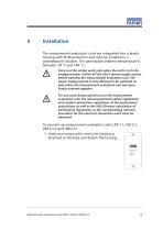
Installation The measurement evaluation units are integrated into a plastic housing with IP 40 protection and must be installed in a weatherproof location. The permissible ambient temperature is between -20 °C and +40 °C. Carry out the wiring work only when the unit is in its deenergised state. Switch off the 230 V power supply system before opening the measurement evaluation unit. The power supply system is only allowed to be switched on only when the measurement evaluation unit has been firmly screwed together. For any work being carried out on the measurement evaluation unit, the...
カタログの9ページ目を開く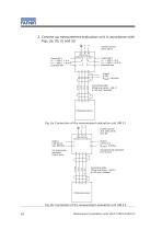
2. Connect up measurement evaluation unit in accordance with Figs. 2a, 2b, 2c and 2d. N - Output 0–10V RLoad ≥ 10 kOhm Connecting cable Filling level sensor – UM 2.1 4 x 0,5 mm2, shielded Filling level sensor Fig. 2a: Connection of the measurement evaluation unit UM 2.1 L1 (-) not galvanically separated from 3 and 4 + Output 0 V bis 10 V - RLoad ≥ 10 kOhm not galvanically separated from 3 and 4 Connecting cable Filling level sensor – UM 2.2 4 x 0.5 mm2, shielded Filling level sensor Fig. 2b: Connection of the measurement evaluation unit UM 2.2 Measurement evaluation units UM 2.1/
カタログの10ページ目を開く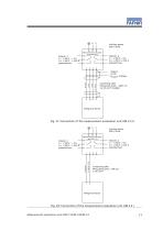
- Output 0–10V + R Load ≥ 10 kOhm Connecting cable Filling level sensor – UM 2.3 U 4 x 0.5 mm2, shielded Filling level sensor Fig. 2c: Connection of the measurement evaluation unit UM 2.3 U N Connecting cable Filling level sensor – UM 2.3 I 2 x 0.5 mm2 Filling level sensor Fig. 2d: Connection of the measurement evaluation unit UM 2.3 I Measurement evaluation units UM 2.1/UM 2
カタログの11ページ目を開く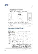
3. Replace the housing and screw it on. 4. Finally turn on the power supply. The green LED „Operation“ and „Power“ are lit. Hersteller: FAFNIR GmbH Hamburg Hersteller: FAFNIR GmbH Hamburg Hilfsenergie: 230 V Ausgang: 0(4)–20mA max. 500 W Betrieb Test Power Test FAFNIR GmbH Hamburg Measurement evaluation unit UM 2.2 is now ready for operation. Measurement evaluation unit UM 2.3 still has to be configured and matched to the respective tank data. Finally, the two limit values are set on measurement evaluation units UM 2.1 and UM 2.3. Measurement evaluation unit UM 2.1 Setting limit values To...
カタログの12ページ目を開く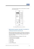
and switches off again when the filling height is exceeded with a value of 23 %. Messauswertung Typ UM 2.1 Hersteller: FAFNIR GmbH Hamburg Fig. 3: Measurement evaluation unit UM 2.1 Measurement evaluation units UM 2.3 U and UM 2.3 I Configuring measurement evaluation units When the measurement evaluation unit has been connected up to the level sensor and the power supply, it has to be configured for correct indication of the level of liquid and hence for the respective tank data. The following parameters are configured in this order: 1. Decimal point (on the display) 2. Decimal point (on...
カタログの13ページ目を開くFAFNIR GmbHのすべてのカタログと技術パンフレット
-
 TORRIX M12 MOBILE
2 ページ
-
 TORRIX XTS
2 ページ
-
 TORRIX 6
1 ページ
-
 LPG Sensors
8 ページ
-
 SEPARIX
8 ページ
-
 Process Automation
28 ページ
-
 O²-PID
4 ページ
-
 COMS Leaflet
4 ページ
-
 VAPORIX Flow and Control
40 ページ
-
 Wallmounting Typ 907
4 ページ
-
 QE 200
4 ページ
-
 TORRIX HART
28 ページ
-
 TORRIX RS485 Modbus
16 ページ
-
 TORRIX M12
40 ページ
-
 FAFNIR Hart Setup
9 ページ
-
 LS 300 / 500
7 ページ
-
 76 A / NB 220
5 ページ
-
 76 / NB 220
2 ページ
-
 SECON-X
4 ページ
-
 PRESSURIX
12 ページ
-
 Insite360
4 ページ
-
 Plugs
Plugs12 ページ
-
 UM 2.1/UM 2.2/UM 2.3
20 ページ
-
 TORRIX-HART
28 ページ
-
 DIVELIX
8 ページ
-
 CONDURIX-HART
28 ページ
-
 CONDURIX
24 ページ
-
 VAPORIX
12 ページ
-
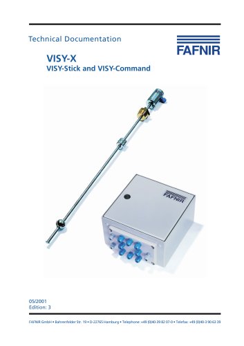
 VISY-X
24 ページ
-
 Accessories
3 ページ
-
 VISY-Command Web
4 ページ
-
 VISY-Reed
4 ページ
-
 VISY-RF
2 ページ
-
 VISY-Stick
15 ページ
-
 VISY-TD Display
2 ページ
-
 VISY-View Touch
2 ページ
-
 TORRIX
10 ページ
-
 TORRIX CI
1 ページ
-
 TORRIX RS485
3 ページ
-
 UM-X Transducer
3 ページ
-
 TEMPERIX
8 ページ
-
 VISY-Command
5 ページ
-
 LPG-Sensoren
8 ページ


カタログアーカイブ
-
 2019 VISY-Stick Flex
2 ページ
-
 2016 VISY-Stick Flex
2 ページ
-
 HPH Ex d
3 ページ
-
 VISY-Monitor
2 ページ
-
 VISY-X LON
10 ページ
-
 SEPARIX
23 ページ
-
 VAPORIX Flow/Control
32 ページ
-
 VISY-Setup V 3.1.0
40 ページ
-
 VISY-Setup V2.10
42 ページ
-
 VISY-View
24 ページ