グループ: Gilbarco Veeder-Root

カタログの抜粋
Technical Documentation CONDURIX-HART The potentiometric level sensor with HART Protocol
カタログの1ページ目を開く
Page 2/28 CONDURIX with HART Protocol
カタログの2ページ目を開く
© Copyright: Reproduction and translation only with the written consent of the FAFNIR company. FAFNIR reserves the right to make product modifications without prior notice. HART® is a registered trademark of the HART Communication Foundation. CONDURIX with HART Protocol Page 3/28
カタログの3ページ目を開く
This specification is designed to complement other CONDURIX documents (e.g. CONDURIX Technical Documentation). It provides a complete description of the CONDURIX Field Device from a HART Communication point of view. The FAFNIR GmbH potentiometric sensor CONDURIX complies with the HART Protocol Revision 6. This document describes all the device specific features and documents HART Protocol implementation details. The functionality of the CONDURIX is described in a way that allows its proper application in a process and its complete support in HART capable Host Devices. This document assumes...
カタログの4ページ目を開く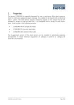
The sensor CONDURIX is especially designed for use in continuous filling level measurement or continuous separating layer coverage. It is suitable for all liquids with conductivity over 1 pS/cm. The level sensor outputs measuring signals in the range 4 to 20 mA. Available in lengths of 200 to 6,000 mm, it is compatible with a variety of tank dimensions. It also comes in the following versions: • CONDURIX Mono (single electrode) • CONDURIX DU (counter electrode) • CONDURIX MA (slotted metal tube) The Ex-approved version of the level sensor can be installed in potentially...
カタログの5ページ目を開く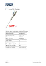
The name plate is located on the CONDURIX probe head. Page 6/28 CONDURIX with HART Protocol
カタログの6ページ目を開く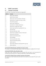
All HART Rev. 6 Universal Commands are supported. CMD Id Function 0 Read Unique Identifier 1 Read Primary Variable 2 Read Loop Current And Percent Of Range 3 Read Dynamic Variables And Loop Current 8 Read Dynamic Variable Classification 9 Read Device Variable With Status 11 Read Unique Identifier Associated With Tag 13 Read Tag, Descriptor, Date 14 Read Primary Variable Transducer Information 15 Read Device Information 16 Read Final Assembly Number 18 Write Tag, Descriptor, Date 19 Write Final Assembly Number 21 Read Unique...
カタログの7ページ目を開く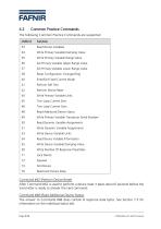
4.2 Common Practice Commands The following Common Practice Commands are supported. CMD Id Function 33 Read Device Variables 34 Write Primary Variable Damping Value 35 Write Primary Variable Range Value 36 Set Primary Variable Upper Range Value 37 Set Primary Variable Lower Range Value 38 Reset Configuration Changed Flag 40 Enter/Exit Fixed Current Mode 41 Perform Self Test 42 Perform Device Reset 44 Write Primary Variable Units 45 Trim Loop Current Zero 46 Trim Loop Current Gain 48 Read Additional Device Status 49 Write Primary Variable Transducer...
カタログの8ページ目を開く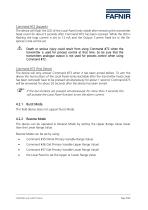
Command #72 (Squawk) The device will flash the LED of the Local Panel (only visible after removing the transmitter head cover) for about 5 seconds after Command #72 has been received. While the LED is flashing the loop current is set to 12 mA and the Output Current Fixed bit in the Response Code will be set. A Death or serious injury could result from using Command #72 when the transmitter is used for process control at that time. So be sure that the transmitters analogue output is not used for process control when using Command #72. Command #73 (Find Device) The device will only answer...
カタログの9ページ目を開く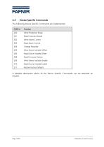
4.3 Device Specific Commands The following Device Specific Commands are implemented: CMD Id Function 200 Write Protection Mode 201 Read Protection Mode 202 Write Alarm Current 203 Read Alarm Current 205 Write Device Variable Offset 206 Read Device Variable Offset 208 Read Firmware Version 209 Write Device Variable Enable 210 Read Device Variable Enable 211 Restore Factory Defaults A detailed description about all the Device Specific Commands can be obtained on request. Page 10/28 CONDURIX with HART Protocol
カタログの10ページ目を開く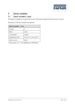
The Device Variable 0 contains the result of the level measurement done by the sensor. Summary of Device Variable 0 properties: * see Section 13.1.1 for additional information. CONDURIX with HART Protocol Page 11/28
カタログの11ページ目を開く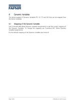
Dynamic Variables The device supports 4 Dynamic Variables (PV, SV, TV and QV) that can be mapped from the Device Variables. Mapping of the Dynamic Variables Use Command #50 (Read Dynamic Variable Assignments) to get the current mapping of the Dynamic Variables. To change the mapping use Command #51 (Write Dynamic Variable Assignments). For the default mapping of the Dynamic Variables see Annex B. CONDURIX with HART Protocol
カタログの12ページ目を開く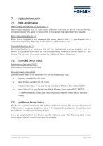
Non-Primary Variable Out Of Limits (bit 1) Non-Primary Variable Out Of Limits is set whenever the value of one of the Non-Primary Variables exceeds the upper or lower limit of the sensor that belongs to this variable. More Status Available (bit 4) More Status Available is set whenever the sensor detects that it is not dripped into a conductive liquid (Dry Warning) or when Device Malfunction is set. Device Malfunction (bit 7) Device Malfunction is set whenever the Self-Test has detected a serious problem with the device. This problems will also set the corresponding Additional Device Status...
カタログの13ページ目を開く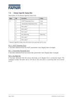
Description of the Device Specific Status bits: * Device Specific Status bits that are not used are set to zero. Bit 0 - HART Parameter Error It has been detected that the HART parameters have illegally been changed. Bit 1 - Transmitter Parameter Error It has been detected that the transmitter parameters have illegally been changed. Bit 5 - Dry Warning It has been detected that the sensor electrode is not dipped into a conductive liquid. The analogue output has been set to 3.8 mA or 20,5 mA (this is a warning and not a sensor error). Page 14/28 CONDURIX with HART Protocol
カタログの14ページ目を開く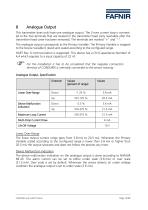
8 Analogue Output This transmitter does only have one analogue output. The 2-wire current loop is connected to the two terminals that are located in the transmitter head (only reachable after the transmitter head cover has been removed). The terminals are marked "+" and "-". The analogue output corresponds to the Primary Variable. The Primary Variable is mapped to the Device Variable 0 (level) and scaled according to the configured range. HART Rev. 6 communication is supported. This device has a CN (Capacitance Number) of 4,4 which equates to a input capacity of 22 nF. For the installation...
カタログの15ページ目を開くFAFNIR GmbHのすべてのカタログと技術パンフレット
-
 TORRIX M12 MOBILE
2 ページ
-
 TORRIX XTS
2 ページ
-
 TORRIX 6
1 ページ
-
 LPG Sensors
8 ページ
-
 SEPARIX
8 ページ
-
 Process Automation
28 ページ
-
 O²-PID
4 ページ
-
 COMS Leaflet
4 ページ
-
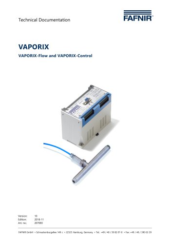 VAPORIX Flow and Control
40 ページ
-
 Wallmounting Typ 907
4 ページ
-
 QE 200
4 ページ
-
 UM 2.1/2.2/2.3
20 ページ
-
 TORRIX HART
28 ページ
-
 TORRIX RS485 Modbus
16 ページ
-
 TORRIX M12
40 ページ
-
 FAFNIR Hart Setup
9 ページ
-
 LS 300 / 500
7 ページ
-
 76 A / NB 220
5 ページ
-
 76 / NB 220
2 ページ
-
 SECON-X
4 ページ
-
 PRESSURIX
12 ページ
-
 Insite360
4 ページ
-
 Plugs
Plugs12 ページ
-
 UM 2.1/UM 2.2/UM 2.3
20 ページ
-
 TORRIX-HART
28 ページ
-
 DIVELIX
8 ページ
-
 CONDURIX
24 ページ
-
 VAPORIX
12 ページ
-
 VISY-X
24 ページ
-
 Accessories
3 ページ
-
 VISY-Command Web
4 ページ
-
 VISY-Reed
4 ページ
-
 VISY-RF
2 ページ
-
 VISY-Stick
15 ページ
-
 VISY-TD Display
2 ページ
-
 VISY-View Touch
2 ページ
-
 TORRIX
10 ページ
-
 TORRIX CI
1 ページ
-
 TORRIX RS485
3 ページ
-
 UM-X Transducer
3 ページ
-
 TEMPERIX
8 ページ
-
 VISY-Command
5 ページ
-
 LPG-Sensoren
8 ページ


カタログアーカイブ
-
 2019 VISY-Stick Flex
2 ページ
-
 2016 VISY-Stick Flex
2 ページ
-
 HPH Ex d
3 ページ
-
 VISY-Monitor
2 ページ
-
 VISY-X LON
10 ページ
-
 SEPARIX
23 ページ
-
 VAPORIX Flow/Control
32 ページ
-
 VISY-Setup V 3.1.0
40 ページ
-
 VISY-Setup V2.10
42 ページ
-
 VISY-View
24 ページ