カタログの抜粋

Magnetically Coupled Rodless Slides FGYSR Series
カタログの1ページ目を開く
FGYSR Series Magnetically coupled rodless slides Features 1. Lube retainers, internal & external. 2. Stainless steel barrel. 3. Anodized aluminum end covers. 4. Bores ø 10, 15, 20, 25, 32, 40 5. The external slider is magnetically coupled to the piston to provide a space-saving rodless slide. 6. Slide position sensors and shock absorbers available. See pages 4 and 7. See page 3 for dimensions and page 7 for sensor selection. How to order Bore Size ø10 ø15 ø20 ø25 ø32 ø40 Min. operating pressure 26 psi Magnet holding force (N) 53.9 137 231 363 588 922 Max. operating pressure 0.7 MPa...
カタログの2ページ目を開く
FGYSR Series Magnetically coupled rodless slides FGYSR Series
カタログの3ページ目を開く
FGYSR Series Magnetically coupled rodless slides Vertical Operation Intermediate Stopping 1) Intermediate stopping of load using an external stopper. When stopping a load in mid-stroke using an external the prescribed values may lead to dropping the load. Also see mounting orientation Example 3 on page 5. operation exceeding these limits can break the magnetic connection. When the cylinder is mounted vertically or at an angle from is required at the stroke end or mid-stroke, use an external stopper for precise positioning. 2) Intermediate stopping of load using an air pressure circuit. When...
カタログの4ページ目を開く
FGYSR Series Magnetically coupled rodless slides Allowable load mass calculation based Calculation (seeTable 2 below left): on cylinder mounting orientation Load Sizing Maximum load mass centered on the slide block when used on strokes less than or equal to the stroke values shown in Table 1. Two factors: Stroke Length & Mounting Orientation Example 1- allowable load calculation for FGYSR25 X 650 size due to limitation from bending of the guide shafts. (Take note of the coefficient.) Additionally, depending on the mounting orienta- Given: Load centered; 2) Horizontal mounting (wall...
カタログの5ページ目を開く
FGYSR Series Magnetically coupled rodless slides Allowable load mass calculation based on cylinder mounting orientation 6) Load center offset in operating direction (Lo) 4) Inclined operation (In operating direction) Bore (mm) ø25 ø32 ø40 ø10 ø15 ø20 Allowable load mass (WA) 3.5 + Lo 5.0 +Lo 6.0 + Lo 6.0 + Lo 7.0 + Lo 8.0 + Lo (kg) Lo = Distance from center of slide block to load center of gravity (cm) Example 6– allowable load calculation for FGYSR25 X 650 load mass (WA) 3.5cos +2(2.2+Lo)sin 5cos +2(2.7+Lo)sin 6cos +2(2.9+Lo) sin (kg) Bore (mm) load mass (WA) 6cos +2(3.4+Lo) sin 7cos...
カタログの6ページ目を開く
FGYSR Series Magnetically coupled rodless slides Shock absorber prices – See table on page 4 separately from charts here. Female Cord Sets 1 Meter 2 Meters 5 Meters Sensor Type Remove this clamp screw and use the fastener supplied with the slide unit. Sensor Selection Guide Electrical Characteristics Quick Disconnect* Reed (LED) 5-120 VDC/VAC, 0.03 Amp Max current, 4 Watt Max., 2.0 voltage drop Electronic (LED) Sourcing PNP 5-28 VDC, 0.20 Amp Max current, 0.5 voltage drop Electronic (LED) Sinking NPN 5-28 VDC, 0.20 Amp Max current, 0.5 voltage drop *Note: Quick disconnect styles are...
カタログの7ページ目を開く
Fabco-Air Product Catalog Library
カタログの8ページ目を開くFABCO-AIRのすべてのカタログと技術パンフレット
-
 Pneumatic Linear Slides
82 ページ
-
 NFPA Air Cylinders
16 ページ
-
 F-Series Air Cylinders
64 ページ
-
 FKHT Series
4 ページ
-
 FVH-16
1 ページ
-
 H-Series Air Cylinders
32 ページ
-
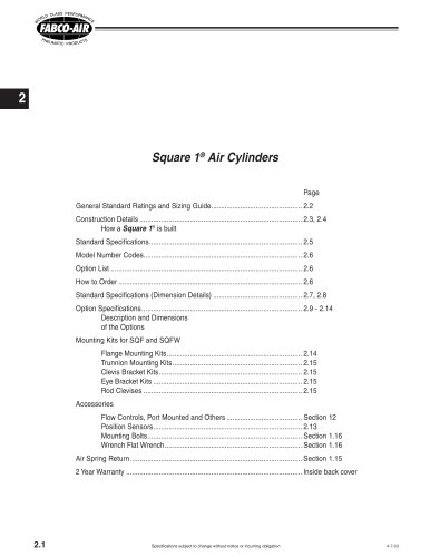 Square 1® Air Cylinders
15 ページ
-
 FKHQ Gripper
4 ページ
-
 NFPA Cylinders
8 ページ
-
 FGYB & FGYR Series
12 ページ
-
 FJU Series Catalog
8 ページ
-
 FKA Gripper Catalog
4 ページ
-
 Gripper Catalog
24 ページ
-
 Pancake® II Catalog
28 ページ
-
 Air-Oil Tanks
4 ページ
-
 FKHT Gripper Catalog
4 ページ
-
 FDH Finger Slide
8 ページ
-
 Master Catalog
200 ページ
-
 FDF Twin Rod Catalog
4 ページ
-
 Vacuum Generator
1 ページ
-
 Micro-Mist Separator
1 ページ


カタログアーカイブ
-
 Pneumatic Grippers
24 ページ