カタログの抜粋

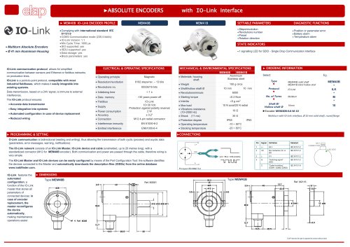
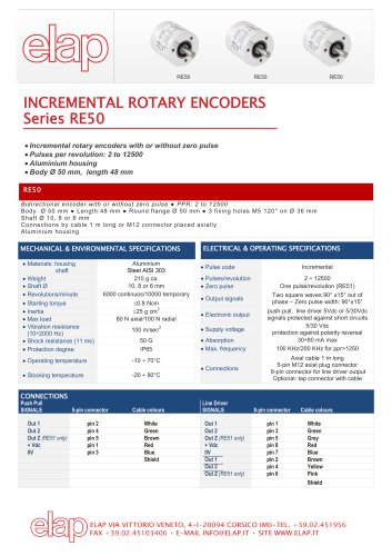
RE/REM Round Flanged INCREMENTAL ROTARY ENCODERS Incremental rotary encoders with or without zero pulse Pulses per revolution: 2 to 12500 Aluminium housing Several configurations available MECHANICAL VERSIONS RE520 • REM520 Body Ø: 58 mm Flange Ø: 58 mm Servo coupling Centering mask Ø 50 mm Shaft Ø 6, 8, 9.52, 10 mm SYNCHRO FLANGE RE540 • REM540 Body Ø: 58 mm Flange Ø: 58 mm Centering mask Ø 36 mm Shaft Ø 6, 8, 9.52, 10 mm RE530 • REM530 Body Ø: 58 mm Flange: RE0444 Shaft Ø 11 mm Aluminium CLAMPING FLANGE PULSES PER REVOLUTION Series RE MECHANICAL & ENVIRONMENTAL SPECIFICATIONS Materials: housing shaft Weight RE/REM 520 • 540 RE/REM530 Aluminium AISI 303 steel 400 g ca Revolutions/minute Starting torque Intertia Max load Vibration resistance (10÷2000 Hz) Shock resistace (11 ms) Protection degree Operating temperature Stocking temperature ELECTRICAL & OPERATING SPECIFICATIONS Pulse code Pulses per revolution Zero reference pulse Output signals Electronic outputs 100 m/sec2 50 G IP65 / optional IP66 with sealing ring* Supply voltage Absorption Max frequency Two square waves 90° ±15° out of phase – Zero pulse width: 90°±15° push-pull, NPN open collector*, 5Vdc or 5/30 Vdc line driver signals protected against short circuits 5/30 Vdc protection against polarity reversal 30÷80 mA max 100/200 KHz for ppr>1250 Axial or radial cable 3 m long /1 m for line driver output Axial or radial MS connector, 7-pin/10pin for line driver output **Max operating speed with
カタログの1ページ目を開く
CONNECTIONS SIGNALS Out 1 Out 2 Out Z RE/REM5x1 + Vdc 0V Non-connected Non-connected Earth Push Pull – Open Collector NPN 7-pin connector Cable colours DIAGRAM 1 DIAGRAM 2 A B C D F E G White Green Brown Red Blue Shield Line Driver 7-pin connector DIAGRAM 3 without 0 pulse A B D F C E G Cable colours 10-pin connector Cable colours DIAGRAM 4 with 0 pulse White A White Green B Green C Grey Red D Red E Red Blue F Blue Brown G Brown Yellow H Yellow I Pink J Shield OUTPUT SIGNALS PP Push-pull OC NPN Open Collector (RE only) LD Line-driver SHAFT Ø 6 -8 – 9.52 - 10 RE/REM530: 11 mm CONNECTIONS...
カタログの2ページ目を開く
REFERENCES Further information and dimensional drawings at the following links: https://www.elap.it/incremental-encoders/encoder-re520/ https://www.elap.it/incremental-encoders/encoder-rem/
カタログの4ページ目を開くELAPのすべてのカタログと技術パンフレット
-
 Linear potentiometers
12 ページ
-
 MEM-Bus EtherCAT®
2 ページ
-
 HLS Wire Encoder
2 ページ
-
 General Catalogue
12 ページ
-
 KD Optical scale
2 ページ
-
 VD4 Digital Readout
2 ページ