グループ: Cubic

カタログの抜粋
Product Name: Single Beam NDIR CO2 Sensor Module Item No.: CM1106S Version: V0.1 Date: October 14, 2019
カタログの1ページ目を開く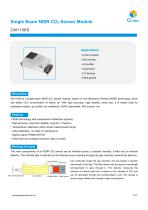
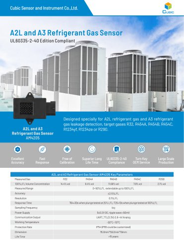
Single Beam NDIR CO2 Sensor Module CM1106S Applications ▪ HVAC industry ▪ IAQ monitor ▪ Air purifier ▪ Automotive ▪ IoT devices ▪ Plant growth Description CM1106S is a single beam NDIR CO2 sensor module, based on non-dispersive infrared (NDIR) technology, which can detect CO2 concentration of indoor air. With high accuracy, high stability, small size, it is widely used for ventilation system, air purifier, air conditioner, HVAC transmitter, IAQ monitor, etc. ▪ NDIR technology with independent intellectual property ▪ High accuracy, long term stability, long life (>10years) ▪ Temperature...
カタログの3ページ目を開く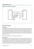
Typical Application Circuit Application scene: UART TTL serial port output Description of Calibration Auto Calibration: Rough installing, non-correct soldering and transportation might result in a reducing of sensor reading accuracy and zero drift, sensor will correct the drift by the built-in self-correcting logic. Powering on the sensor for 7 days continuously, it will record the lowest CO2 concentration measurement value during these 7 days. Sensor will do auto calibration after 7 days and will regard the outdoor fresh air CO2 concentration (400ppm) as baseline. In order to ensure the...
カタログの6ページ目を開く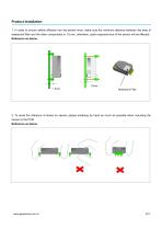
Product Installation 1. In order to ensure airflow diffusion into the sensor inner, make sure the minimum distance between the area of waterproof filter and the other components is 1.5 mm, otherwise, quick response time of the sensor will be effected. Reference as below: 2. To avoid the influence of stress on sensor, please soldering by hand as much as possible when mounting the sensor to the PCB. Reference as below:
カタログの7ページ目を開く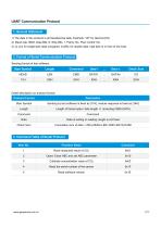
UART Communication Protocol 1. General Statement 1).The data in this protocol is all hexadecimal data. Example: “46” for decimal [70]. 2). Baud rate: 9600, Data Bits: 8, Stop Bits: 1, Parity: No, Flow control: No. 3). [x x] is for single-byte data (unsigned, 0-255); for double data, high byte is in front of low byte. 2. Format of Serial Communication Protocol Sending format of test software: Start Symbol Detail description on protocol format: Protocol Format Start Symbol Sending by test software is fixed as [11H], module response is fixed as [16H] Length of frame bytes= data length +1...
カタログの8ページ目を開く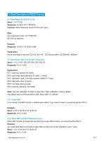
re-open ABC function, you should set the DF2=0. function and set the calibration cycle 7 days. 4.1 Read Measured Result of CO2 Send: 11 01 01 ED Response: 16 05 01 DF1- DF4 [CS] Function: Read measured result of CO2 (Unit: ppm) Note: CO2 measured result = DF1*256+DF2 DF3 DF4 is reserved Example: Response: 16 05 01 02 58 00 00 8B Explanation: Hex is converted to decimal: 02 is 02; 58 is 88 CO2 concentration =02*256+88 = 600ppm 4.2 Open/Close ABC and Set ABC Parameter Send: 11 07 10 DF1 DF2 DF3 DF4 DF5 DF6 CS Response: 16 01 10 D9 Explanation: DF1: reserved, default 100 (0x64) DF2: open/close...
カタログの9ページ目を開く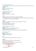
4.2.3 Change the Calibration Cycle The calibration cycle is 7 days by default. For example, if you want to change the calibration cycle to 10 days, you should set the DF3=10. Example: Send: 11 07 10 64 00 0A 01 90 64 75 Response: 16 01 10 D9 4.3 Calibration of CO2 Concentration Send: 11 03 03 DF1 DF2 CS Response: 16 01 03 E6 Function: Calibration of CO2 concentration Note: 1. Calibration target value = DF1*256+DF2 Unit: PPM, range (400-1500ppm) 2. Before calibration, please make sure CO2 concentration in current ambient is calibration target value. Keeping this CO2 concentration for two 2...
カタログの10ページ目を開く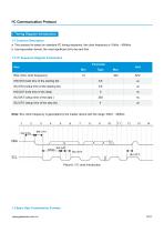
I²C Communication Protocol 1. Timing Diagram Introduction 1.1 Common Description a. This protocol is based on standard I2C timing sequence, the clock frequency is 10kHz~400kHz. b. Use big-endian format, the most significant bit to be sent first. 1.2 I2C Sequence Diagram Introduction Item fSCL (SCL clock frequency) tHD.STA (hold time of the starting bit) tSU.STA (setup time of the starting bit) tHD.DAT (hold time of the data) tSU.DAT (setup time of the data ) tSU.STO (setup time of the stop bit) Note: SCL clock frequency is generated by the master device with the range 10khz~400khz. 1.3...
カタログの11ページ目を開く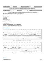
Picture 2: The general data format sends from the master device to the slave S Picture 3: The general data format received from the slave device to the master device The meaning of the symbol in picture 1.2 and picture 1.3: S: start condition SA: slave address W: write bit R: read bit A: acknowledge bit ~A: not acknowledge bit D: data, each data is 8bit P: stop condition Shadow: The signal generated from the master device No Shadow: The signal generated from the slave device 1.4 Timing Diagram Picture 4: The address byte sent from the master device Picture 5: The master device read a byte...
カタログの12ページ目を開く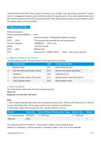
The performance of the MCU which is used in the sensor is not very high. If you use I/O port to simulate I2C master device, it is suggested to reserve a period before and after ACK signal (such as 100 us), after sending every byte (8 bit) to leave enough time for the SCM to process the data. Within requirements of speed, it is recommended to lower the reading speed as much as possible. 2.1 Statement of Measuring Command The slave address is 0x31, the data command of the slave device is as below: CO2 measuring result: DF0*256+DF1, Fixed output is 550ppm during preheating period Status bit:...
カタログの13ページ目を開く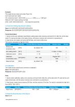
Example: The master device reads some data: Read 3 bit. 0x01 0x03 0x20 0x01 0xDB CO2 measuring result = (0x03 0x20) hexadecimal = (800) decimal = 800 ppm Status bit: 0x01 means working normally [CS]= -(0x01+0x03+0x20+0x01) Only keep the lowest bite. 2.3 Auto Zero Setting Specification Setting Send: 0x10 [DF0] [DF1] [DF2] [DF3] [DF4] [DF5] Response: [0x10] [DF0] [DF1] [DF2] [DF3] [DF4] [DF5] [CS] Format description: 1. Sensor will be auto calibration specification setting status after receiving command 0x10. After this, all the data which I2C read are the data in this status format, until...
カタログの14ページ目を開く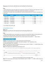
1. Sensor starts device code output status once receiving the command 0x1 F. After this, all the data which I2C read will be such status format data, until the sensor receives new command or re-powering on. 2. Data format, the master device receives [DF0] first, and then receives [CS] at last. The result is calculated by hig h bit in front. Diagram: The master device read two bytes continuously from the slave device. The slave machine address: 0x31 = 0110001 (the machine address is 7 bit) + read/write bit (1 bit) The slave data address: 0x01 = 00000001 Step 1: The master device sends the...
カタログの15ページ目を開くCubic Sensor and Instrument Co.のすべてのカタログと技術パンフレット
-
 Gasboard-7500H-OPC
13 ページ
-
 Gas Sensor Line-up
1 ページ
-
 About Cubic
1 ページ
-
 Gasboard-7020
4 ページ
-
 Gasboard-7500
7 ページ
-
 Gasboard 3400P
5 ページ


カタログアーカイブ
-
 RHB Series
8 ページ
-
 Opacity meter
1 ページ