
カタログの抜粋
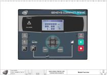
GENSYS COMPACT PRIME HMI / CORE STANDARD WIRING SCHEMATICS Module Front view
カタログの3ページ目を開く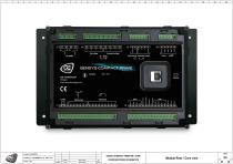
GENSYS COMPACT PRIME HMI / CORE STANDARD WIRING SCHEMATICS Module Rear / Core view PAGE 04 ◄ ► 03 05
カタログの4ページ目を開く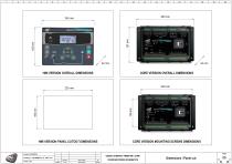
GENSYS COMPACT PRIME HMI / CORE STANDARD WIRING SCHEMATICS Dimensions / Panel cut PAGE
カタログの5ページ目を開く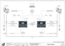
GENSYS COMPACT PRIME HMI / CORE STANDARD WIRING SCHEMATICS Single line diagram
カタログの6ページ目を開く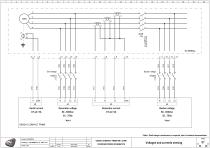
GENSYS COMPACT PRIME Created: 09/05/2019 Generator voltage 80...500Vac 35...75Hz * Note 1 GENSYS COMPACT PRIME HMI / CORE STANDARD WIRING SCHEMATICS Busbar voltage 80...500Vac 35...75Hz * Note 1 Note1: Shall voltage transformers be required, refer to technical documentation Voltages and currents sensing PAGE 07 ◄ ► 06 08
カタログの7ページ目を開く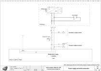
To breaker / engine control To inputs / outputs circuitry Module power supply 7...38vVdc * Note 1 GENSYS COMPACT PRIME * Note1: Example given with use of a 24Vdc battery charger, but applies identically with 12Vdc PAGE GENSYS COMPACT PRIME HMI / CORE FIRST RELEASE STANDARD WIRING SCHEMATICS Power supply and shield connection 07
カタログの8ページ目を開く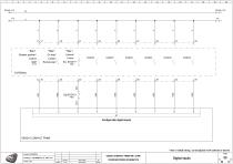
GENSYS COMPACT PRIME HMI / CORE STANDARD WIRING SCHEMATICS Digital inputs PAGE 09 ◄ ► 08 10
カタログの9ページ目を開く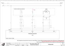
Module +Vcc SENSOR CONNECTION EXAMPLES Module +Vcc Configurable analog inputs * Note 1 GENSYS COMPACT PRIME * Note1: Analog inputs can be used with resistive sensors (max. range 0-500 Ohms), with external 20mA current transducers fitted with a 30-ohm 1/4 Watt resistor or as additional digital inputs ** Note2: Ensure engine body and 0Vcc are connected in case of use of a single-wire sensor *** Note3: The common analog input terminal must have a direct connection to the –Batt terminal of the controller PAGE GENSYS COMPACT PRIME HMI / CORE FIRST RELEASE STANDARD WIRING SCHEMATICS
カタログの10ページ目を開く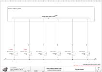
GENSYS COMPACT PRIME Configurable digital outputs J1 Fuel valve / Spare Starter / Spare * Note1: Maximum output current is 1.8 Amps ** Note2: External relay recommended for starter & fuel valve controls PAGE GENSYS COMPACT PRIME HMI / CORE FIRST RELEASE STANDARD WIRING SCHEMATICS
カタログの11ページ目を開く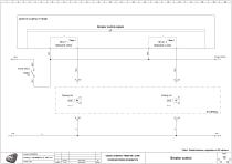
GENSYS COMPACT PRIME Breaker control outputs J3 * Note 1 RELAY 2 BREAKER CLOSE * Note 1 RELAY 1 BREAKER OPEN Opening coil Closing coil * Note1: Default functions, adjustable via PC software PAGE GENSYS COMPACT PRIME HMI / CORE FIRST RELEASE STANDARD WIRING SCHEMATICS
カタログの12ページ目を開く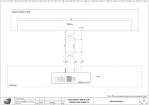
GENSYS COMPACT PRIME ENGINE PICK UP EXTERNAL * Note1: Refer to the engine technical sheet to set the number of teeth PAGE GENSYS COMPACT PRIME HMI / CORE FIRST RELEASE STANDARD WIRING SCHEMATICS
カタログの13ページ目を開く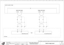
GENSYS COMPACT PRIME Voltage control output Speed control output SPEED REGULATOR VOLTAGE REGULATOR * Note1: Settings vary upon the type of regulator used. Refer to the technical sheet for more information PAGE GENSYS COMPACT PRIME HMI / CORE FIRST RELEASE STANDARD WIRING SCHEMATICS Speed & voltage control 13
カタログの14ページ目を開く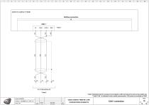
GENSYS COMPACT PRIME TO OTHER MODULES ** Note 2 * Notel: Embedded 120-ohm resistance to be bridged to CAN H terminal on first and last bus module only ** Note2: CAN 1 is dedicated to inter-module communication. CAN options are available on CAN2 GENSYS COMPACT PRIME HMI / CORE STANDARD WIRING SCHEMATICS
カタログの15ページ目を開く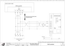
GENSYS COMPACT PRIME Distance between node and module should not exceed 30 centimeters Notel: Bus end 120-ohm resistor to be placed between CAN L and CAN H terminal on last equipment only GENSYS COMPACT PRIME HMI / CORE STANDARD WIRING SCHEMATICS
カタログの16ページ目を開く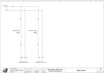
GENSYS COMPACT PRIME HMI / CORE STANDARD WIRING SCHEMATICS Engine control PAGE 17 ◄ ► 16 18
カタログの17ページ目を開く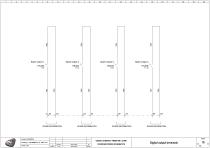
GENSYS COMPACT PRIME HMI / CORE STANDARD WIRING SCHEMATICS Digital output terminals PAGE 18 ◄ ► 17
カタログの18ページ目を開くCRE TECHNOLOGYのすべてのカタログと技術パンフレット
-
 gensys 2.0 range
4 ページ
-
 SCR 2.0
2 ページ
-
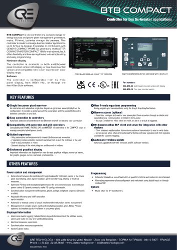 BTB COMPACT
4 ページ
-
 I4GEN.10
2 ページ
-
 I4GEN suite
2 ページ
-
 DC/DC Converters
2 ページ

カタログアーカイブ
-
 ICGEN2.0
55 ページ
-
 Battery chargers
24 ページ
-
 C2S
C2S16 ページ
-
 product applications
4 ページ
-
 GENSYS 2.0 CORE
4 ページ
-
 BP range
2 ページ
-
 i4GEN
i4GEN2 ページ
-
 TRAININGS SESSIONS
4 ページ
-
 BATTERY CHARGERS
4 ページ
-
 avrcompact
2 ページ
-
 MARINE SOLUTIONS
4 ページ
-
 Synchro Compact
144 ページ
-
 COMPACT RANGE
4 ページ


