
カタログの抜粋
Quick Start Guide Cisco 250 Series Smart Switches
カタログの1ページ目を開く
Welcome Thank you for choosing the Cisco 250 Series Smart Switch. These switches are designed to be operational right out-of-the-box as a standard switch. In the default configuration, it forwards packets between the connecting devices after powered up. Package Contents • Cisco 250 Series Smart Switch • Rackmount Kit • Power Cord or Adapter • This Quick Start Guide • Pointer Card with China RoHS • Technical Support Contacts • EU Directives 1999/5/EC Compliance Information (for EU SKU only) This guide familiarizes you with the smart switch layout and describes how to deploy the switch in...
カタログの2ページ目を開く
• Computer with Internet Explorer (version 9.0, 10.0, 11.0), or Firefox (version 36.0, 37.0, or higher), or Chrome (version 40,41,42 or higher) for using the web-based interface. Mounting the Cisco 250 Series Smart Switches There are three ways to install the switch: • Place the switch on a flat surface. To place the switch on a desktop, install the four rubber feet (included) on the bottom of the switch. • Mount the switch in a standard rack (1 rack unit high). • Mount on a wall. Placement Tips Do not mount the device in a location where any of the following conditions exist: • High...
カタログの3ページ目を開く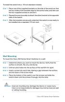
To install the switch into a 19-inch standard chassis: STEP 1 Place one of the supplied brackets on the side of the switch so that the four holes of the brackets align to the screw holes, and then use the four supplied screws to secure it. STEP 2 Repeat the previous step to attach the other bracket to the opposite side of the switch. STEP 3 After the brackets are securely attached, the switch is now ready to be installed into a standard 19-inch rack. Wall Mounting To mount the Cisco 250 Series Smart Switches to a wall: STEP 1 Determine where you want to mount the device. Verify that the...
カタログの4ページ目を開く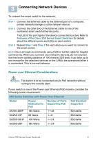
Connecting Network Devices To connect the smart switch to the network: STEP 1 Connect the Ethernet cable to the Ethernet port of a computer, printer, network storage, or other network device. STEP 2 Connect the other end of the Ethernet cable to one of the numbered smart switch Ethernet ports. The LED of the port lights if the device connected is active. Refer to Features of the Cisco 250 Series Smart Switches for details about the different ports and LEDs on each switch. STEP 3 Repeat Step 1 and Step 2 for each device you want to connect to the smart switch. NOTE Cisco strongly recommends...
カタログの5ページ目を開く
Consider the following when connecting switches capable of supplying PoE: The PoE models of the switches are PSE (Power Sourcing Equipment) that are capable of supplying DC power to attaching PD (Powered Devices). These devices include VoIP phones, IP cameras, and wireless access points. The PoE switches can detect and supply power to pre-standard legacy PoE Powered Devices. Due to the support of legacy PoE, it is possible that a PoE switch acting as a PSE may mistakenly detect and supply power to an attaching PSE, including other PoE switches, as a legacy PD. Even though PoE switches are...
カタログの6ページ目を開く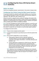
Configuring the Cisco 250 Series Smart Switches Before You Begin Verify the managing computer requirements in the product release notes. Configuring Your Switch Using the Web-based Interface To access the switch by using the web-based interface, you must know the IP address the switch is using. The switch uses the factory default IP address of 192.168.1.254, with a subnet of /24. When the switch is using the factory default IP address, the System LED flashes continuously. When the switch is using a DHCP server-assigned IP address or an administrator has configured a static IP address, the...
カタログの7ページ目を開く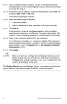
STEP 4 Open a Web browser window. If you are prompted to install an ActiveX plug-in when connecting to the device, follow the prompts to accept the plug-in. STEP 5 Enter the switch IP address in the address bar and press Enter. For example, http://192.168.1.254. The Switch Login Page displays. STEP 6 Enter the default login information: Default password is cisco (passwords are case sensitive) If this is the first time that you have logged on with the default username and password, the Change Password page opens. The rules for constructing a new password are displayed on the page. STEP 8...
カタログの8ページ目を開く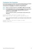
Troubleshoot Your Connection If you cannot access your switch from the web-based interface, the switch may not be reachable from your computer. You can test network connections by using ping on a computer running Windows: STEP 1 Open a command window by using Start > Run and enter cmd. STEP 2 At the Command window prompt enter ping and the smart switch IP address. For example ping 192.168.1.254 (the default IP address of the smart switch). If you can reach the switch, you should get a reply similar to the following: Pinging 192.168.1.254 with 32 bytes of data: Reply from 192.168.1.254:...
カタログの9ページ目を開く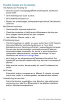
Possible Causes and Resolutions The Switch is not Powering on • Verify the power cord is plugged firmly into the switch and into the power outlet. • Verify that the power outlet is active. • Verify that the computer is on. • Replace the power adapter, before replacing the switch, if the situation continues. Bad Ethernet connection • Check the LEDs for proper indications. • Check the connectors of the Ethernet cable to ensure that they are firmly plugged into the switch and your computer. • Use a different Ethernet cable or port. IP Addressing Issues • The Cisco switches can also be accessed...
カタログの10ページ目を開く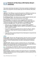
Features of the Cisco 250 Series Smart Switches This section describes the exterior of the smart switches including ports, LEDs, and connections. Not all models have all of the features described. Ports USB Port—The USB port connects the switch to a USB device so that you can save and restore the configuration files, firmware images, and SYSLOG files through the connected USB device. RJ-45 Ethernet Ports—Use these ports to connect network devices, such as computers, printers, and access points, to the switch. SFP (if present)—The small form-factor pluggable (SFP) ports are connection points...
カタログの11ページ目を開くCisco Systems/シスコのすべてのカタログと技術パンフレット
-
 Cisco MDS 9396T
15 ページ
-
 Cisco IP Phone Portfolio
45 ページ
-
 Cisco Catalyst 9000
8 ページ
-
 Cisco 250 Series
17 ページ
-
 Cisco 220
13 ページ
-
 Cisco 200E
8 ページ
-
 Cisco 90 Series
5 ページ
-
 860
8608 ページ


カタログアーカイブ
-
 Cisco 500
7 ページ
-
 809
80916 ページ
-
 PROFINET_c11-351501
5 ページ
-
 MDS 9500
11 ページ
-
 Cisco 5700 Series
8 ページ
-
 500 series
6 ページ
-
 Cisco 2500
7 ページ
-
 Cisco Flex 7500
7 ページ
-
 c78-713207
7 ページ
-
 c78-521631
9 ページ
-
 c78-492032
6 ページ
-
 C78-464240
4 ページ
-
 cisco_prime_
1 ページ
-
 Cisco 4451-X
11 ページ
-
 Cisco Nexus 9300
16 ページ
-
 r42610
18 ページ
-
 NAC
NAC5 ページ
-
 c78-701253
13 ページ
-
 0900aecd802930c5
22 ページ
-
 c78-553913
10 ページ
-
 c78-553971
5 ページ
-
 c78-612808
11 ページ
-
 c78-584157
5 ページ
-
 c36-609138
9 ページ
-
 c78-660124
6 ページ
-
 c78-644629
5 ページ
-
 c78-553980
11 ページ
-
 c78-714747
6 ページ
-
 c78-714744
6 ページ
-
 c78-714745
6 ページ
-
 brochure_c02-717032
2 ページ
-
 brochure_c02-466008
6 ページ
-
 brochure_c02-643975
3 ページ
-
 Cisco_ClientLink
6 ページ
-
 brochure_c02-646027
41 ページ


