カタログの抜粋

Engineering SpecSheet BU-xH1R Base Unit Family Features SDSSS Technology 900MHz @ 10mW, 2.4GHz @ 100mW S One Form C Relay SUp to Five Form A (SPST) Relay Outputs Standard Operation SSingle Connector for Wiring Ease ^Diagnostic LEDs SCAN bus Capable SWeatherproof Case The SmaRT BU-2H1R5 and BU-9H1R5 base units feature one Form C relay output and five Form A relay outputs. CAN bus capable base units — BU-2H1R3 and BU-9H1R3 — have one Form C and three Form A relay outputs. The BU-xH1 R family of base units accepts a broad range of operating input power with model dependent operating voltages of 7-32VDC, 7-28VAC, and 100-240VAC. All connections are made using the single 12-wire cable harness that fits to the base unit keyed connector to guard against cross connection. SmaRT base units feature seamless association to a SmaRT hand-held unit without the need to open the case. Using Direct Sequence Spread Spectrum (DSSS) wireless technology at 900MHz or 2.4GHz, the base unit provides a robust link with a SmaRT hand-held remote in congested radio environments with a line-of-sight communications range of up to 1,000 feet. BU-9H1R3 and BU-2H1R3 CAN units provide a CAN bus interface for applications requiring wired connectivity. The rugged weatherproof enclosure allows the unit to operate worry-free in harsh weather conditions. Radio Frequency RF Power License Modulation Antenna Range Specifications Power Operating Vin See Product Family Listing Table below Outputs Form C Relay (1); Form A Relay (3 - 5, model dependent) 7A max switching @ 45°C 100mA min @ 5VDC 15A max total output Enclosure Dimensions 119 x 133 x 36mm (5.24” x 4.69” x 1.42”) Durability High Impact Polymer 906-924MHz or 2405-2480MHz See Product Family Listing Table below None required, license free DSSS Internal or external by device 1000' (hardware option dependent) Indicators (model dependent) 1 (CAN) Indicates CAN traffic 2 (OUT) Indicates activated relay 5 (PWR) ON - Normal Operation SmaRT BU-xH1R Base Units ©2015 CERVIS, Inc.
カタログの1ページ目を開く
The wiring configuration shown is for a BU-xH1R5 — no CAN connection. For CANbus BU-xH1R3, P7 is CANH and P9 is CANL. JP5 when installed (factory) isolates the Form A relays from the Form C relay. SNote: Cable shields should be grounded only at one end of each shield segment to minimize ground loops. SNote: BU-xH1R-CAN units are internally terminated at 4.3kn. Termination can be removed at the factory. SmaRT BU-xH1R Base Units November 2015
カタログの2ページ目を開く
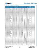
BU-xH1R Product Family Listing SmaRT BU-xH1R Base Units August 2015 ©2015 CERVIS, Inc. S142.4.1-SmaRT BU-xH1R 3
カタログの3ページ目を開く
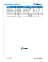
Engineering SpecSheet Model Name SmaRT BU-xH1R Base Units 4November 2015
カタログの4ページ目を開くCervisのすべてのカタログと技術パンフレット
-
BU-9H16AF
2 ページ
-
BU-xH24XF
2 ページ
-
BU-9H18XF
3 ページ
-
BU-xH16F
2 ページ
-
PG - xH12JS
2 ページ
-
BU - x H16R
3 ページ
-
SmaRT BU - xH 6R
3 ページ
-
LongRT Base
2 ページ
-
LongRT Console Box
2 ページ
-
MINExpo 2016
1 ページ
-
TM70 CSA/UL
2 ページ
-
TM70 Handheld
2 ページ
-
IK4
2 ページ
-
iK 3
3 ページ
-
iK 2
2 ページ
-
TM70 Console Box
2 ページ
-
SmaRT Connect
2 ページ
-
SmaRT BU-X00H
2 ページ
-
SmaRT-BU-xH16AF
2 ページ
-
SmaRT BU-XH20XF
2 ページ
-
SmaRT BU-XH18XF
3 ページ
-
SmaRT EBU
2 ページ
-
SmaRT 18 button
2 ページ
-
SmaRT PG-XH12JS
2 ページ
-
SmaRT PG-XH14-DIS
2 ページ
-
SmaRT PG-XH14
2 ページ
-
SmaRT BU-2H8D Series
3 ページ
-
SmaRT BU-9H8D
3 ページ
-
SmaRT BU-xH16R
3 ページ
-
SmaRT BU-xH6R
3 ページ
-
SmaRT Console Box
2 ページ
-
SmaRT MCB
2 ページ
-
SmaRT 10 Button
1 ページ
-
SmaRT 2,4,6 Button
2 ページ
-
Warrior 42-MCB
2 ページ
-
Warrior 32-MCB
2 ページ
-
LongRT Base Unit
2 ページ
-
SmaRT Wireless Catalog
27 ページ


