
カタログの抜粋

DATA SHEET Insertion flowmeter with paddle wheel for continuous flow measurement • Economic integration in pipe systems without any additional piping • 3-wire frequency pulse version to directly interface with PLC’s (both PNP and NPN) • Connection to Bürkert devices in remote versions Product variants described in the data sheet may differ from the product presentation and description. Can be combined with Type 8611 eCONTROL - Universal controller Type 8025 Insertion flowmeter or batch controller with paddle wheel and flow transmitter or remote batch controller Type 8619 multiCELL - Multi-channel and multi-function transmitter/controller 1000011076 | Standard | EU | en | 202009 | 14 © Christian Bürkert GmbH & Co. KG, Subject to alteration Type description The paddle wheel flowmeter for continuous flow measurement is especially designed for use in neutral, slightly aggressive, solid free liquids. The Bürkert designed fitting system ensures simple installation of the devices into all pipes from DN 20…DN 400. The flowmeter produces a frequency pulse signal, proportional to the flow rate, which can easily be transmitted and processed by a Bürkert transmitter/controller.
カタログの1ページ目を開く
Table of contents 1. General technical data 8. Product design and assembly 9. Networking and combination with other Bürkert products Visit product website
カタログの2ページ目を開く
1. General technical data Note: If the device is mounted in a humid environment or outside, then the maximum voltage allowed is 35 V DC instead of 36 V DC. Product properties Material Please make sure the device materials are compatible with the fluid you are using. Detailed information can be found in chapter “3.1. Chemical Resistance Chart – Bürkert resistApp” on page 5. Non wetted parts Housing Union nut Seal Screws Female cable plug/male fixed plug Wetted parts Seal Axis and bearings Sensor armature, paddle wheel Dimensions Measuring principle Compatibility Pipe diameter Measuring range...
カタログの3ページ目を開く
Medium data Fluid temperature With fitting Type S020 in: • PVC: 0…+ 50 °C (+ 32…+ 122 °F) • PP: 0…+ 80 °C (+ 32…+ 176 °F) • PVDF, stainless steel or brass: - 15…+ 80 °C (+ 5…+ 176 °F) See data sheet Type S020 for more information. Fluid pressure Max. PN 10 See data sheet Type S020 for more information. Viscosity Max. 300 cSt Rate of solid particles Max. 1 % 0.5 mm Maximum particle size Process/Port connection & communication Port connection G 2" for use with Type S020 Insertion fitting See data sheet Type S020 for more information. Electrical connection Female cable plug according to EN...
カタログの4ページ目を開く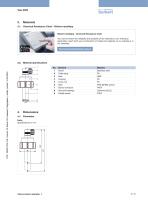
3. Materials 3.1. Chemical Resistance Chart – Bürkert resistApp Bürkert resistApp – Chemical Resistance Chart You want to ensure the reliability and durability of the materials in your individual a pplication case? Verify your combination of media and materials on our website or in our resistApp. Start Chemical Resistance Check Element Screw Cable plug Seal Housing Union nut Seal Sensor armature Axis and bearings Paddle wheel Material Stainless steel PA NBR PE PC FKM (EPDM option) PVDF Ceramics (Al2O3) PVDF Visit product website
カタログの5ページ目を開く
4.2. Flowmeter installed in a S020 fitting Note: Specifications in mm DN 5. Performance specifications 5.1. Pressure temperature diagram Application range for complete device (fitting Type S020 + flowmeter Type 8020) 12 10 8 6 4 2 6. Product installation 6.1. Installation notes Note: The flowmeter is not designed for gas and steam flow measurement. Minimum straight upstream and downstream distances must be observed. According to the pipe’s design, necessary distances can be bigger or use a flow conditioner to obtain the best accuracy. Fore more information, please refer to EN ISO 5167‑1. EN...
カタログの6ページ目を開く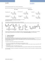
with the associated specified minimum inlet and outlet distances. Make sure that the measuring conditions at the point of measurement are calm and problem-free. DN = Orifice 2 x 90° elbow joint 3 dimensional 90° elbow joint or T-piece 1.) If the valve cannot be mounted after the measuring device, the minimal distances have to be respected. 2.) If an expansion cannot be avoided, the minimal distances have to be respected. Please note minimum flow velocity The flowmeter can be installed into either horizontal or vertical pipes. Important criteria for this are; ensure that the measurement pipe...
カタログの7ページ目を開く
8. Product design and assembly 8.1. Product assembly Note: • The 8020 flowmeter can easily be installed into any Bürkert Insertion fitting system (S020) by just fixing the main nut. • The S020 Insertion fitting ensures simple installation into pipes from DN 20…DN 400. See data sheet Type S020 for more information. The flowmeter 8020 consists of a transducer and a paddle-wheel with ceramic bearings. The ceramic rotating axis is set on the end of an insertion sensor armature. The transducer is mounted inside the armature. 9. Networking and combination with other Bürkert products Example:...
カタログの8ページ目を開く
10.2. Recommendation regarding product selection Note: A complete flow measurement equipment consists of a flowmeter Type 8020 and a Bürkert Insertion fitting Type S020. See data sheet Type S020 for more information. Two different components must be ordered in order to select a complete device. The following information is required: • Article no. of the desired flowmeter Type 8020 (see chapter “10.4. Ordering chart” on page 9) • Article no. of the selected S020 Insertion fitting (See data sheet Type S020 ) 10.3. Bürkert product filter Bürkert product filter – Get quickly to the right...
カタログの9ページ目を開く
For up-to-date addresses please visit us at www.burkert.com Austria Belgium Czech Republic Denmark Finland France Germany Italy Netherlands Norway Poland Spain Sweden Switzerland Turkey United Kingdom Russia China Hong Kong India Japan Korea Malaysia Philippines Singapore Taiwan United Arab Brazil Uruguay Emirates South Africa Credits, © and concept: Christian Bürkert GmbH & Co. KG | Photographs: Marc Eggimann Fotografie - 4051 Basel | Scanner GmbH - Werbeagentur Künzelsau 74653 Künze
カタログの10ページ目を開くBÜRKERT FLUID CONTROL SYSTEMSのすべてのカタログと技術パンフレット
-
 Type 0121
16 ページ
-
 Type 6240
26 ページ
-
 Type 8026
12 ページ
-
 Type 8605
13 ページ
-
 Type 8692
18 ページ
-
 Type 5470
15 ページ
-
 8041
804110 ページ
-
 Type 0498
6 ページ
-
 Type 8081
9 ページ
-
 Type 2300
32 ページ
-
 Type 8012
21 ページ
-
 Type 8110
11 ページ
-
 Type 8010
14 ページ
-
 8222
82228 ページ
-
 Type 8137
12 ページ
-
 Typ 8804
12 ページ
-
 Proportional Valves
17 ページ
-
 Measurement devices
68 ページ
-
 Solenoid valves 6240
9 ページ
-
 Solenoid Valves
31 ページ
-
 6240
624011 ページ
-
 Type 0301
4 ページ
-
 Type 0201
4 ページ
-
 Type 0300
6 ページ
-
 Type 0200
6 ページ
-
 Type 0131
4 ページ
-
 Type 0142
4 ページ
-
 Type 0117
3 ページ
-
 Type 0293
3 ページ
-
 Process & Control Valves
33 ページ
-
 Diaphragm Competence
14 ページ
-
 Standard Product Program
13 ページ
-
 AirLINE SP
2 ページ
-
 multiCELL Type 8619
5 ページ
-
 Flowmeter Type 8045
4 ページ
-
 eControl Type 8611
2 ページ
-
 Dosing Systems
4 ページ
-
 CUT Product Line
9 ページ
-
 CATALOGUE BURKERT SELECT
88 ページ
-
 Cooling Towers
2 ページ
-
 MicroFluidics
2 ページ
-
 Fuel Cell Tech
2 ページ
-
 Robot Welding
2 ページ
-
 Plastic Extruding
2 ページ
-
 Flyer Cooking
2 ページ
-
 Injection Molding
2 ページ
-
 Heat Exchanger
2 ページ
-
 Clean Steam
2 ページ
-
 Food and Beverage
32 ページ
-
 Systemhaus Brochure
8 ページ
-
 Company profile
15 ページ
-
 Cooling Systems Brochure
16 ページ
-
 Water Treatment Brochure
16 ページ
-
 MicroFluidics Brochure
16 ページ
-
 steam products
16 ページ
-
 Product overview Sensors
52 ページ


