
カタログの抜粋

DATA SHEET 3/2 or 4/2 way Solenoid Valve for pneumatics • Compact design in 3/2 and 4/2 way versions • Extendable valve block • Reduced power consumption • Different pneumatic connections available • Robust construction Product variants described in the data sheet may differ from the product presentation and description. Type description Type 2012 Pneumatically operated 2/2 way globe valve CLASSIC Type 2516 Cable plug DIN EN 175301-803 1000390870 | Standard | EU | en | 201905 | 00 © Christian Bürkert GmbH & Co. KG, Subject to alteration Valves of type 5470 consist of a type 6106 pilot rocker solenoid valve and a pneumatic valve. An armature with a tilting bearing, similar o a rocker, tilts within the body of the pilot valve, and switches the valve. The minimal tilting movement of the rocker is non-wearing, and basic lubrication is unnecessary. The type 5470 R is available as a 3/2 and 4/2 way valve. The valves can be mounted together individually using the module flange. In various applications, they can be used advantageously as valve blocks. Different variants are available for service ports 2 and 4. Visit produ
カタログの1ページ目を開く
Table of contents 1. General technical data 4. Product design and assembly Visit product website
カタログの2ページ目を開く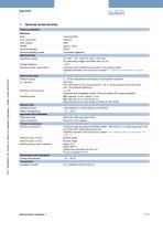
1. General technical data Product properties Materials Body Inner valve parts Seal material Weight Nominal diameter Nominal operating mode Electrical data Operating voltage Voltage tolerance Electrical power consumption Performance data Pressure range QNn value air Electrical nominal power Switching times Medium data Operating media Medium temperature Approvals and certificates Protection class Type of protection Product connections Electrical connection Pressure ports 1 and 3 Pressure ports 1 and 3 Working ports 2 and 4 (variants) Environment and installation Ambient temperature...
カタログの3ページ目を開く
2. Circuit functions Circuit function Description Type: C, solenoid valve 3/2 way Servo-assisted Normally closed Type: D, solenoid valve 3/2 way Servo-assisted Normally open Type: G, solenoid valve 4/2 way Servo-assisted Normally open 3. Dimensions 3.1. Dimensions variants for port connection 1 3.2. Dimensions variants for port connection 2 (working ports) Note: Dimensions in mm Visit product website
カタログの4ページ目を開く
3.3. Dimensions block installation with 18 mm extendable valves on a single base module Structure with connector lugs at side Note: • Dimensions in mm • Electrical connection rectangular plug with 2 pins (cable plug Type 2505 cable and wire version) Block installation 20 Depending on working port Visit product website
カタログの5ページ目を開く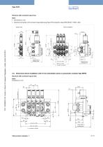
Structure with connector lugs at top Note: • Dimensions in mm • Electrical connection with connector lugs (cable plug Type 2516 protection class IP65 DIN EN 175301 - 803) Block installation Single valve Depending on working port Depending on working port 3.4. Dimensions block installation with 19 mm extendable valves on pneumatic modules Type MP05 Structure with connector lugs at side Note: Dimensions in mm 19 32.5 35.5 Depending on working port Visit product website
カタログの6ページ目を開く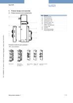
4. Product design and assembly 4.1. Product structure servo-assisted valve 9 Element Manual override Port connection 2 Working port 2 (B) Working port 4 (A) Pressure supply 1 (P) Port connection 1 (FM07 = not equipped) Exhaust 3 (R) Amplifier Pilot control standard Plug contacts at side Connection variants for port connection 1 LTA1 = port connection 1 Base module Base module with check valve in R channel Hose screw connection SL 6/4 mm Visit product website
カタログの7ページ目を開く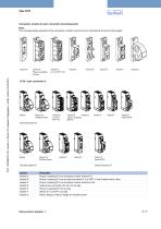
Connection variants for port connection 2 (working ports) Note: The corresponding properties of the connection variants can be found in the table at the end of the chapter. Variant B Plug-in coupling Ø 6mm Namur for throttle screws Variant B Variant D Plug-in coupling Ø6 mm Namur for throttle screws Circuit function C Variant Variant A Variant B Variant C Variant D Variant E Variant F Variant G Circuit function D Properties Plug-in coupling Ø 6 mm at bottom (circuit function C) Plug-in coupling Ø 6 mm at side and sleeve G ⅛ or NPT ⅛ with throttle check valve Plug-in coupling Ø 6 mm at...
カタログの8ページ目を開く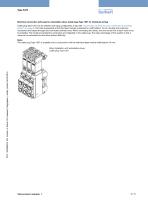
Electrical connection with plug for extendable valves (cable plug Type 1057 for individual wiring) Cable plug Type 1057 can be selected with plug configuration at top (see “Connection variants for port connection 2 (working ports)” on page 8). The main prerequisite is that the base module is selected for width/station 18 mm. Neutral and protective conductors are looped through and connected centrally once. When connecting the valves, only the control line to each valve must be installed. The neutral and protective conductors are integrated in the cable plug. The major advantage of this...
カタログの9ページ目を開く
4.2. Product structure block installation with 18 mm extendable valves on individual base module Structure with connector lugs at side 1 Element Connection module on left Extendable valves Intermediate feed (for different pressures) Extendable valves Connection module on right Structure with connector lugs at top Visit product website Element Connection module on left Extendable valves Intermediate feed (for different pressures) Extendable valves Connection module on right
カタログの10ページ目を開く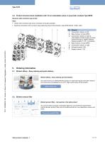
4.3. Product structure block installation with 19 mm extendable valves on pneumatic modules Type MP05 Structure with connector lugs at side Note: • Variant with connector lugs at top: Individual wiring also possible • Electrical connection with connector lugs (cable plug Type 2516 protection class IP65 DIN EN 175301 - 803) 1 Element Connection module, on left Base module, 3x Type MP05 Connection module on right as intermediate module (supply channels pushed through or sealed; different pressure supply P1, P2…is possible) Base module, 2x Type MP05 Connection module, on right Exhaust channel:...
カタログの11ページ目を開く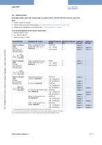
5.3. Ordering chart Extendable single valves with module flange for pressure ports 1 (P) and 3 (R) with connector lugs at top Note: • Further variants on request • Delivery does not include cable plug (see “5.4. Ordering table accessories” on page 13) • Details on the illustrated circuit functions see “2. Circuit functions” on page 4 The following applies to all the variants listed below: • Nominal width: .0 mm 4 • QNn value air: 300 l/m • Pressure range: 2...10 bar Circuit function Voltage/Frequency Effective coil power [V/Hz] [W] 24/DC/UC 2 Type: C, solenoid valve 3/2 way Servo-assisted...
カタログの12ページ目を開くBÜRKERT FLUID CONTROL SYSTEMSのすべてのカタログと技術パンフレット
-
 Type 0121
16 ページ
-
 Type 6240
26 ページ
-
 Type 8020
10 ページ
-
 Type 8026
12 ページ
-
 Type 8605
13 ページ
-
 Type 8692
18 ページ
-
 8041
804110 ページ
-
 Type 0498
6 ページ
-
 Type 8081
9 ページ
-
 Type 2300
32 ページ
-
 Type 8012
21 ページ
-
 Type 8110
11 ページ
-
 Type 8010
14 ページ
-
 8222
82228 ページ
-
 Type 8137
12 ページ
-
 Typ 8804
12 ページ
-
 Proportional Valves
17 ページ
-
 Measurement devices
68 ページ
-
 Solenoid valves 6240
9 ページ
-
 Solenoid Valves
31 ページ
-
 6240
624011 ページ
-
 Type 0301
4 ページ
-
 Type 0201
4 ページ
-
 Type 0300
6 ページ
-
 Type 0200
6 ページ
-
 Type 0131
4 ページ
-
 Type 0142
4 ページ
-
 Type 0117
3 ページ
-
 Type 0293
3 ページ
-
 Process & Control Valves
33 ページ
-
 Diaphragm Competence
14 ページ
-
 Standard Product Program
13 ページ
-
 AirLINE SP
2 ページ
-
 multiCELL Type 8619
5 ページ
-
 Flowmeter Type 8045
4 ページ
-
 eControl Type 8611
2 ページ
-
 Dosing Systems
4 ページ
-
 CUT Product Line
9 ページ
-
 CATALOGUE BURKERT SELECT
88 ページ
-
 Cooling Towers
2 ページ
-
 MicroFluidics
2 ページ
-
 Fuel Cell Tech
2 ページ
-
 Robot Welding
2 ページ
-
 Plastic Extruding
2 ページ
-
 Flyer Cooking
2 ページ
-
 Injection Molding
2 ページ
-
 Heat Exchanger
2 ページ
-
 Clean Steam
2 ページ
-
 Food and Beverage
32 ページ
-
 Systemhaus Brochure
8 ページ
-
 Company profile
15 ページ
-
 Cooling Systems Brochure
16 ページ
-
 Water Treatment Brochure
16 ページ
-
 MicroFluidics Brochure
16 ページ
-
 steam products
16 ページ
-
 Product overview Sensors
52 ページ


