
カタログの抜粋

Safety switching device for sensors with 8,2 kΩ Translation of the original instructions General 85 LED LCD display “Mode” button “Data” button Terminals Safety Instructions • ead these operating instructions thoroughly before putting the device into R operation and keep them for future reference. • o not use this product other than for its specified application. D • Only trained and qualified personnel may install and initialize the device. • nly authorized factory personnel may perform hardware/software changes or O repairs to the product. • Pay attention to all local relevant electrical safety regulations! • ailure to follow these safety precautions may cause damage to device or F objects, serious personal injury, or death. • t is the responsibility of the equipment installer to carry out a risk assessment I and to install the system, in compliance with applicable local, national and international regulations, safety standards, codes and laws as well as the Machinery Directive 2006/42/EC, should this apply. • Observe all applicable local, national, and international door safety standards, codes, and laws. • lways consider the safety functions of your applications as a whole, never just A in relation to one individual section of the system. • he installer is responsible for testing the system to ensure it meets all T applicable safety standards. • uring the operation of electrical components D – e. g. in the case of a short circuit hot and ionised gases can be emitted; protection covers must not be removed! • The device should only be operated from a safety extra low voltage (SELV) system with safe electrical separation according to EN 61558. • The wiring must be protected against mechanical damage. Prior to starting installation or mounting, take the following safety precautions: • Check the voltage data on the label of the switching device. • Ensure that the device/installations cannot be switched on! • Ensure that the power supply is disconnected! • Protect the device with a housing against contamination or harsh environments! • Cover any neighbouring live parts or remove them! • Disconnect device from mains in the event of a fault. • Avoid touching any electronic components. • Limited protection against accidental contact! Intended use The EsGate 3 switching devices are used to monitor the manufacturer's pressuresensitive protective devices (for safety edges according to EN ISO 13856-2) on industrial gates/doors. They comply with the requirements of the standard EN ISO 13849-1 for protective devices up to PL e, Cat. 3. If the safety device is not requested operationally at least once a month, it must be checked automatically or manually by the operator at least once a month. The device can be installed in a simple, industri
カタログの1ページ目を開く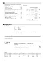
Function Connected sensors with a terminating resistor of 8.2 kΩ are monitored for a change in current. In the idle mode • ll safety outputs are conductive a • he LED lights up green t • oth dots on the display flash b When one or more sensors are actuated • he total resistance of the sensor system drops towards zero Ω t • he defined switching threshold is not reached anymore t • the corresponding Safety output opens • he LED lights up orange, P appears on the display t Block diagram Function and safety check Voltage supply Configuration and set-up 4.1 Terminals Supply voltage (24 V AC/DC)...
カタログの2ページ目を開く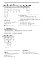
4.4 Diagnostic menu (read only) › Enter Diagnostic menu: Press “Mode” and “Data” buttons simultaneously for 2 seconds → Status LED flashes orange To see the next parameter, press “Mode”, Data query (Mode E and r): press “Data” Exit Diagnostic menu: › Press “Mode” button for 2 seconds Fall-delay time Errors flash both outputs Access Configuration (see chapter 4.5) E last 5 error messages (displayed by pressing “Data”) r current resistances of the sensors (displayed in kΩ: 1, 2, 4, 6, 8, 10, 12 or 14) S shows the state of output 1: output activated, 1 = current flow = okay, E = no current...
カタログの3ページ目を開く
Hardware version Software version Internal temperature Errors flash Errors flash Supply voltage Enter Service mode: Press “Data” for 10 seconds → Green status LED flashes To show the next parameter, press “Mode” Data query in each mode: press “Data” button Exit Service mode: Press “Mode” button for 2 seconds In the service mode, further information can be displayed: H Hardware Version S Software Version t Type (Cat. acc. to EN ISO 13849-1) U Internal supply voltage o Current chip temperature E The last five error messages (displayed by pressing “Data”) E press and hold “Data” button until...
カタログの4ページ目を開くBBC Bircher Smart Accessのすべてのカタログと技術パンフレット
-
 Safety mats
8 ページ
-
 S-Line
4 ページ
-
 PrimeMotion C
2 ページ
-
 RegloBeam 2
2 ページ
-
 EsGate 2
4 ページ
-
 PrimeMotion B
2 ページ
-
 PIR 20
4 ページ
-
 PrimeTec A
4 ページ
-
 Herkules 2E
4 ページ
-
 ProLoop2
4 ページ
-
 ProAccess
4 ページ
-
 ExpertSystem XL
4 ページ
-
 EsMatix 3
2 ページ
-
 CleanSwitch
4 ページ
-
 LBDoor
4 ページ
-
 ProLoop Lite
4 ページ
-
 ArtMotion 2
2 ページ
-
 CleanSwitch
4 ページ
-
 CR3
CR32 ページ
-
 SpotScan
4 ページ
-
 EsMatix 3
2 ページ
-
 UniScan
4 ページ
-
 Sensorama 2019
8 ページ
-
 Passive Infrared
1 ページ
-
 Light Sensors
1 ページ
-
 Light Barriers
1 ページ
-
 Merkur 2
6 ページ
-
 Brochure Safety Mats
8 ページ
-
 Sensorama 2014
8 ページ
-
 CareMat®
4 ページ
-
 TopScan
4 ページ
-
 PIR20
PIR204 ページ
-
 PIR30
PIR304 ページ
-
 ProLoop
4 ページ
-
 UniScan
4 ページ


