グループ: ASCON TECNOLOGIC Group

カタログの抜粋

proceeding with the installation of to the European Directives. on Directives and Standards used for controller can be found in the file: table with: zip. requires special equipment and specialised on directly by the user. For this purpose, the repair service for its Customers. information. and electromagnetic compatibility are note.
カタログの3ページ目を開く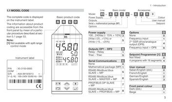
5 1 - Introduction – model Accessories Colour User manual Setpoint C D E F G 0 A 3 5 5 B 1 5 C 0 2nd SSR drive/analogue output (OP6) 4 Options D None 0 6 7 8 Setpoint Programmer [1] E Not fitted 0 4 programs with 16 segments 4 User manual F Italian/English (std.) 0 French/English 1 German/English 2 Spanish/English 3 Front panel colour G Dark (std.) 0 Beige 1 Frequency input 1 Frequency input + OP6 6 1
カタログの6ページ目を開く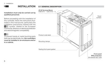
Front panel IP65 protection EN 650529 (IEC 529) Panel surface
カタログの7ページ目を開く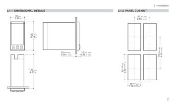
7 2 - Installation PANEL CUT-OUT 65 mm min 2.56 in min 45+0.6 mm 1.78+0.023 in 3.62+0.031 in 113 mm min 4.45 in min
カタログの8ページ目を開く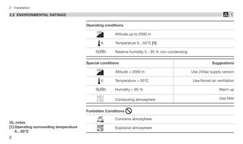
B condensing Use filter Warm up Use forced air ventilation Use 24Vac supply version Suggestions
カタログの9ページ目を開く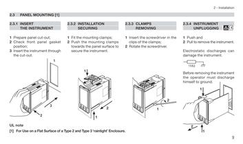
9 2 - Installation the 2.3.4 INSTRUMENT UNPLUGGING B 1 Push and 2 Pull to remove the instrument. Electrostatic discharges can damage the instrument. Before removing the instrument the operator must discharge himself to ground. 1MÙ 2 1 1
カタログの10ページ目を開く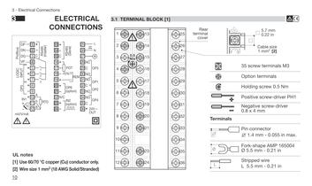
Terminals Cable size 1 mm2 [2] 5.7 mm 0.22 in B 35 screw terminals M3 Option terminals Holding screw 0.5 Nm Positive screw-driver PH1 Negative screw-driver 0.8 x 4 mm Pin connector q 1.4 mm - 0.055 in max. Fork-shape AMP 165004 Ø 5.5 mm - 0.21 in Stripped wire L 5.5 mm - 0.21 in
カタログの11ページ目を開く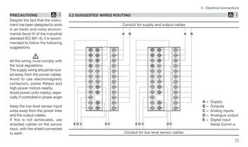
28 27 30 29 26 25 31 32 33 34 35 36 A B 11 3 - Electrical Connections cables cables B A = Supply B = Outputs C = Analog inputs D = Analogue output E = Digital input Serial Comm.s
カタログの12ページ目を開く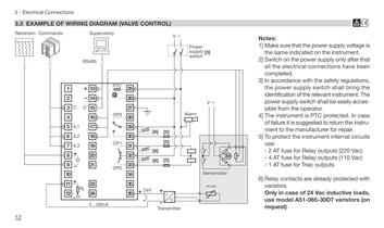
B Notes: Make sure that the power supply voltage is the same indicated on the instrument. Switch on the power supply only after that the electrical connections have been completed. accordance with the safety regulations, the power supply switch shall bring the identification of the relevant instrument. The power supply switch shall be easily accessible from the operator. The instrument is PTC protected. In case failure it is suggested to return the instrument to the manufacturer for repair. protect the instrument internal circuits use: AT fuse for Relay outputs (220 Vac) AT fuse for Relay...
カタログの13ページ目を開く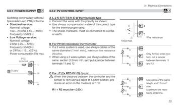
13 3 - Electrical Connections B Wire resistance 150Ù max. Only for two wires system, put a jumper between terminals 11 and 12. Use wires of the same length and 1.5 mm2 size. Maximum line resistance 20 Ù/line. 10 11 12 A B A R2 R1 10 11 12 A b B 11 12
カタログの14ページ目を開く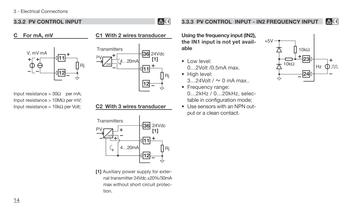
INPUT - IN2 FREQUENCY INPUT B IN2), available selectable mode; output +5V 23 24 10kÙ 10kÙ Hz
カタログの15ページ目を開く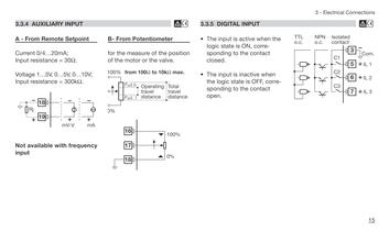
15 3 - Electrical Connections B the corresponding 3 7 6 TTL o.c. Isolated contact Com. IL 3 IL 2 C2 C3 5 NPN o.c. IL 1 C1
カタログの16ページ目を開く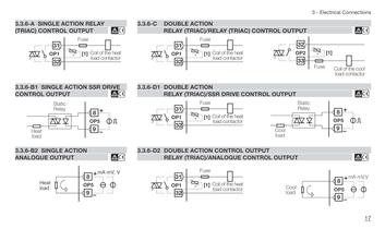
17 3 - Electrical Connections CONTROL OUTPUT B OUTPUT B OUTPUT B Fuse Coil of the cool load contactor 32 33 OP2 [1] Cool load Static Relay 8 9 OP5 8 9 Cool OP5 load mA mV,V
カタログの18ページ目を開く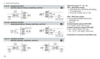
Notes for pages 17 - 18 - 19 - OP2 Relay output SPST Relay N.O., 2A/250 Vac (4A/120Vac) for resistive load, Fuse 2AT at 250V, 4AT at 110V. - OP2 Triac output O. contact for resistive load of up to 1A/250 Vac max. Fuse 1AT Isolated digital outputs OP5-OP6 0…24Vdc, ±20%, 30 mA max. Isolated analogue outputs OP5-OP6 4…20mA, 750Ù / 15V max. 1…5V, 0…10V, 500Ù / 20mA max. Varistor for inductive load 24Vac only
カタログの19ページ目を開く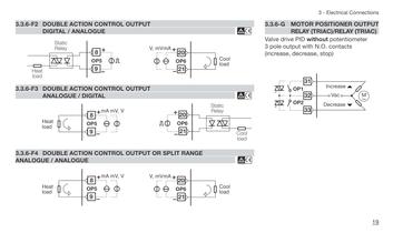
19 3 - Electrical Connections 3.3.6-G MOTOR POSITIONER OUTPUT RELAY (TRIAC)/RELAY (TRIAC) Valve drive PID without potentiometer pole output with N.O. contacts increase, decrease, stop) OP1 33 32 31 OP2 Vac Decrease Increase M~
カタログの20ページ目を開く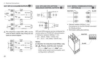
SERIAL COMMUNICATIONS (OPTION) [2] B Galvanic isolation 500Vac/1 min; Compliance to the EIA RS485 standard Modbus/Jbus; Termination setting dip switches. C C MASTER SLAVE 1 2 3 13 14 15 1 2 3 4 MASTER SLAVE
カタログの21ページ目を開く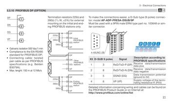
B 21 3 - Electrical Connections concerning wiring and cables can be found on Guide or on Internet at: online/list 33 easier, a D-Sub type (9 poles) connector: PRESA-DSUB/9P male ERNI type part no. 103648 or similar Signal Description according to PROFIBUS specifications TxD-P (DP) Receive data/transmission data plus TxD-N (DN) Receive data/transmission data negative VP) (DG) Data transmission potential (ground to 5V) Supply voltage of the terminating resistance-P, (P5V)
カタログの22ページ目を開く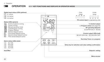
MODE Over range Under range SP operating Setpoint (Local/Remote or Stored) % Control output or Program status (see page 64) Control output LEDs (red) åOP1/OP4 ON - çOP2/OP4 OFF Run/stop Timer or a program selection and value setting confirmation Setpoint setting Menu access 8_8_8_8_ -8-8-8-8 PV control input in engineering units
カタログの23ページ目を開く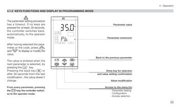
23 4 - Operation value mnemonic parameter selection confirmation modification menu for: setting selection
カタログの24ページ目を開く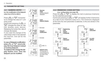
SETTING page 26) display the next or previous mnemonic or %will display further mnemonics every 0.5 s. The mnemonic displayed parameter is selected, is the one stored in the Unit °f Unit none Unit ph Degree Fahrenheit no units defined Ph
カタログの25ページ目を開く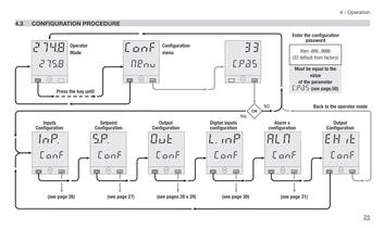
25 4 - Operation EHit ALM Conf Conf (see page 31) Back to the operator mode Enter the configuration password Must be equal to the value of the parameter C.Pas (see page.50) from -999...9999 (33 default from factory) Alarm s configuration Output Configuration
カタログの26ページ目を開く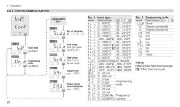
Hertz ph Hz PInp . 1112°F request Engineering 122.0°F 572.0°F 1112°F 752°F 2912°F 2912°F 2192°F 1112°F Value Description éUnit Tab. 2 Engineering units none None rh °C Degree centigrade °f Degree Fahrenheit Rh MA mA MU mV U Volt Ph bar bar psI PSI Frequency 3272°F 2192°F 1112°F 3632°F 3632°F 2012°F Notes: [1] NiChroSil-NiSil thermocouple. [2] Ni-Mo thermocouple.
カタログの27ページ目を開く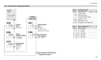
27 4 - Operation Tab. 4 Rem. Setpoint Value Description 0=5 0…5 Volt 1=5 1…5 Volt 0=20 0…20 mA Tab. 3 4=20 4…20 mA Setpoint type 0=10 reM.t Remote - trim 0…10 Volt érs.In loc.t Local - trim l=r Local/remote only reM Remote only loc Local only Value Description éS.P.ty Prog Programmed (option)
カタログの28ページ目を開くASCON TECNOLOGICのすべてのカタログと技術パンフレット
-
 NP4
NP42 ページ
-
 ZIS EIIRLIBGPMAT2018
1 ページ
-
 KR1E
KR1E4 ページ
-
 ClimaPAC
8 ページ
-
 at on cloud
8 ページ
-
 Z31/Y39 - Data sheet
4 ページ
-
 CATALOGO PRODOTTI 2014/2015
113 ページ
-
 Refrigeration catalogue 2016
168 ページ
-
 TCPDE M
2 ページ
-
 Sensitive Touch
4 ページ
-
 opmt
opmt2 ページ
-
 m81
m816 ページ
-
 MP02
MP022 ページ
-
 Deltadue series
8 ページ
-
 Gammadue series
8 ページ
-
 IO-CB series
4 ページ
-
 Paperless recorder
4 ページ


カタログアーカイブ
-
 TRH-MINI
3 ページ
-
 TRH52
TRH524 ページ
-
 TRH21
TRH214 ページ
-
 Pneumatic Actuators
7 ページ


