グループ: Angst+Pfister

カタログの抜粋
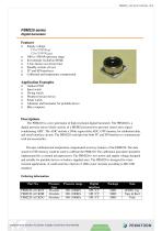
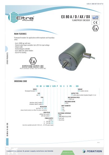
PBM220 series Digital barometer Supply voltage: 1.7 to 5.5V(VDD) 1.2 to 5.5V(VDDIO) 300 to 1100 hPa pressure range 8cm altitude resolution (RMS) 2.2ms fastest conversion time Standby current <0.1μA I2C and SPI interfaces Calibrated and temperature compensated Outdoor PND Sport watch Diving watch Weather forecast device Smart watch Altimeter and barometer for portable device Bike computer Descriptions The PBM220 is a new generation of high resolution digital barometer. The PBM220 is a digital pressure sensor which consists of a MEMS piezoresistive pressure sensor and a signal conditioning ASIC. The ASIC include a 24bits sigma-delta ADC, OTP memory for calibration data, and serial interface circuits. The PBM220 could provide both I2C and SPI interface to communicate with microcontroller. Pressure calibrated and temperature compensated were key features of the PBM220. The data stored in OTP memory could be used to calibrate the PBM220. The calibration procedure should be implemented by a external microprocessor. The PBM220 is low power and supply voltage designed and suitable for portable devices or battery-supplied ones. The PBM220 is designed for water resistant applications. It could meet the criterion of 100m water resistant according to ISO 2281 standard. Ordering information Part No. Pressure type Absolute Absolute Absolute Pressure range
カタログの1ページ目を開く
Competitive sensor & power supply solutions worldwide
カタログの2ページ目を開く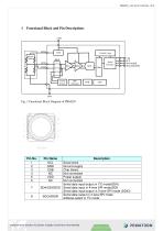
Functional Block and Pin Descriptions VDD Pressure Sensor Control Logic Temp Sensor Fig. 1 Functional Block Diagram of PBM220 Serial clock Ground supply Chip Select Not connected Power supply Not connected Serial data input/output in I2C mode(SDA) SDA/SDI/SDIO Serial data input in 4-wire SPI mode(SDI) Serial data input/output in 3-wire SPI mode (SDIO) Serial data output in 4-wire SPI mode SDO/ADDR Address select in I2C mode
カタログの3ページ目を開く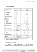
2 Elect^i^^l Cl^racteristic Parameter 1. All the data were measured with 3V supply voltage at a temperature of 25±3°C, unless otherwise noted. 2. Maximum error of pressure reading over the pressure range after offset adjusted at one pressure point. 3. Maxi mum error of press urn reading over th e pressure range. 4. According to 32 bit integer compensation formula._ Competitive sensor & power supply solutions worldwide
カタログの4ページ目を開く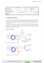
Competitive sensor & power supply solutions worldwide
カタログの5ページ目を開く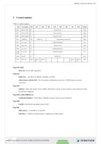
5 Control registers Table 5.1 control registers Reg 0xF6-0xF8 Data_out: 24 bitt ADO output data Reg 0xF4 CtSR<l:0>: 00:1024X, 01:2048X, 10:4096X, 11:8192X MeasuremenVeontroFcS:01-: lOinO. rnficate t temperature conversion. 1 lOlOO.mdicate a pressure conversion. Reg OxER Softreset:Write only reg(t1eu pf setto 0tB6,wiUpeefcum a powes anrene1 ieedeeae. Autoeelnmed to 0 after Cte softreset completed. Reg {OxFl, OxDO, euBBaOxAAp CaliOfoOion Registers : Total 20bytes calibration registers used for sensor calibration. Reg 0x6B PartID: 8 bits IirnO yD r the de>nulO ealue ie tx4a. Reg...
カタログの6ページ目を開く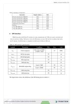
Table 5.2 Summary of instructions Competitive sensor & power supply solutions worldwide
カタログの7ページ目を開く
Figure 6.1 SPI timing diagram The falling edge of CSB, in conjunction with the rising edge of SCLK, determines the start of framing. Once the beginning of the frame has been determined, timing is straightforward. The first phase of the transfer is the instruction phase, which consists of 16 bits followed by data that can be of variable lengths in multiples of 8 bits. If the device is configured with CSB tied low, framing begins with the first rising edge of SCLK. The instruction phase is the first 16 bits transmitted. As shown in Figure 5.2, the instruction phase is divided into a number of...
カタログの8ページ目を開く
Data follows the instruction phase. The amount of data sent is determined by the word length (Bit WO and Bit W1). This can be one or more bytes of data. All data is composed of 8-bit words. Data can be sent in either MSB-first mode or LSB-frrst mode (by setting ‘LSB_tirst’ bit). On power up, MSB-first mode is the default. This can be changed by programming the configuration register. In MSB-first mode, the serial exchange starts with the highest-order bit and ends with the LSB. In LSB-lirst mode, the order is reversed. (Figure 6.3) CSB \/ SCL don'tcare^ Q A A A A A A A H A A H A H A A H...
カタログの9ページ目を開く
Table 7.2 Electrical specification of the I2C interface pins Symbol Clock frequency Setup Time for a repeated start condition Hold time for a start condition Setup Time for a stop condition Time before a new transmission can start Figure 7.1 I2C Timing Diagram The I2C interface protocol has special bus signal conditions. Start (S), stop (P) and binary data conditions are shown below. At start condition, SCL is high and SDA has a falling edge. Then the slave address is sent. After the 7 address bits, the direction control bit R/W selects the read or write operation. When a slave device...
カタログの10ページ目を開く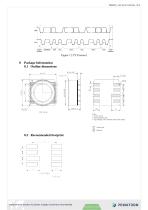
START ADCRRSSFA ACK DATA ACK STOP VA Contact pads F0 Dielectric Competitive sensor & power supply solutions worldwide
カタログの11ページ目を開く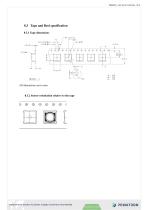
All dimensions are in mm. 8.3.2 Sensor orientation relative to the tape £ e e 0 e e e t r L Competitive sensor & power supply solutions worldwide
カタログの12ページ目を開く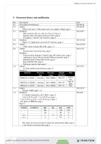
First edition (Preliminary)_ : Fill ed in the spec, of Maxmian enarover suppty itoltage, page 4 M eg: fI wavrform, R^O.^Fi^O^, Fj^g.ti. r, pig. A. ^steetable, description related to 0xF4, page 6 I2C address “ 11011 11”-CnsTl 0(11 l°,page 9_ M td: Figure. 4.1Apc^licft^en circuitfor l2Cmtsrfave, page 5_ : 8ms pressrre aonvers8oe timr, jr^e ] Modified: Function blocg diagracn: Cich^Lo.ms-^Control Logic, page 3 Apjrhnatian circuit: Microcontrillor-^ Microcontroller, page 5 Reg0xF6-0xF8 ^Rsg 0xF6-0xF8- pafp 9 3gfxE0 Rf Rearran^EjlreBir man. nwHUa mu nnnm 8.3 Tage and Real spxcification, pgge...
カタログの13ページ目を開く
1.3 Modified: 8.1 Outline dimensions, removed the solder layer, page 11 Competitive sensor & power supply solutions worldwide
カタログの14ページ目を開く
PBM220_100-33-421-003-EH-1216 PEI/LPOT30N am emberofthe Angst + Pfister Group Sales Switzerland & Liechtenstein Sales International Key Accounts Sales Germony Sales Austria kurt.stritzelberger@pewatron.com dieter.hirthe@pewatron.com Sales OtherCountries / Product Manag eree c9 Sensors Physical tcrmors Data Acquisition Thomas Clausen Phone+41 r^4 6^yf9 0C 13 thomas.clecren @ 20W2 tron .co m Geometrical Sensors E-Components Current Serreos Mmn Mactinrlntaefrco Measurement Probes Sebastiano Leggio Phone+41 44 877 35 06 sebastiano.leggio@pewatron.com Competitive sensor & power supply solutions...
カタログの15ページ目を開くAngst+Pfister Sensors and Power AGのすべてのカタログと技術パンフレット
-
 SQ-UST_L_0105-01
4 ページ
-
 SQ-UST_L_0104-01
4 ページ
-
 SQ-UST_L_0103-01
4 ページ
-
 SQ-UST_L_0003-01
3 ページ
-
 SQ-UST_L_0002-01
3 ページ
-
 SQ-UST_L_0001-01
3 ページ
-
 PFLOW Series
5 ページ
-
 Model PFLOW3000 Series
16 ページ
-
 Model PFLOW2001 Series
14 ページ
-
 PZA-MC25-N/P
2 ページ
-
 PEWA100
9 ページ
-
 HLP-80H series
5 ページ
-
 HLP-40H series
5 ページ
-
 HBG-60P series
6 ページ
-
 UHP-750 series
6 ページ
-
 XLG-50 seri es
9 ページ
-
 DAP-04 series
8 ページ
-
 POB-30 series
11 ページ
-
 RHP-1U Rack System
9 ページ
-
 RFP-M8M4-5A
5 ページ
-
 RFP-M5M3-3A
4 ページ
-
 RFP-M2M3-3A
4 ページ
-
 RFP-M1M3-3A
4 ページ
-
 NCL CL1 01
4 ページ
-
 IRL RGB 01
4 ページ
-
 IRL CL2 01
4 ページ
-
 MSR385WD
3 ページ
-
 MSR145WD
3 ページ
-
 MSR 145
3 ページ
-
 M2029
M20293 ページ
-
 MSR165
3 ページ
-
 CRM102.1
33 ページ
-
 CRM200
39 ページ
-
 CRM100
37 ページ
-
 FPM
FPM4 ページ
-
 FGN
FGN4 ページ
-
 FPN
FPN4 ページ
-
 PBM220-A14N series
14 ページ
-
 PBM220 series
15 ページ
-
 PBM210-A20K Series
14 ページ
-
 STX Series – Model 13A
11 ページ
-
 CCD Series – Model 54D
20 ページ
-
 APB2Series
5 ページ
-
 AP4Series
5 ページ
-
 AP2Series
5 ページ
-
 PHPS-7500 OEM
6 ページ
-
 PPCP3-M1
10 ページ
-
 AG4Series
6 ページ
-
 AG2Series
5 ページ
-
 New Pewatron brochure
11 ページ
-
 GST220A
4 ページ
-
 GSM40B
6 ページ
-
 GSM36B
4 ページ
-
 GSC25E
5 ページ
-
 TDR-480
5 ページ
-
 GC120
GC1204 ページ
-
 HDR-30
5 ページ
-
 GSM220A
6 ページ
-
 EPP-400
5 ページ
-
 ENP-120
5 ページ
-
 ENC-120
6 ページ
-
 ATX-100
4 ページ
-
 RPS-200
7 ページ
-
 APBR30X75
2 ページ
-
 APBR30X60
2 ページ
-
 APBR 30X50 MM
2 ページ
-
 PSB54/16
2 ページ
-
 PSB54/14
2 ページ
-
 PSB36T/16
2 ページ
-
 PSB35T/12
2 ページ
-
 PSB25T/16
2 ページ
-
 PSB25T/12
2 ページ
-
 PSB21/12
2 ページ
-
 PSB 21
2 ページ
-
 AD-Series
16 ページ
-
 DMU11
DMU113 ページ
-
 HDR-30 series
5 ページ
-
 DMU30-01
25 ページ
-
 DMU30
DMU303 ページ
-
 DKA30 serie s
2 ページ
-
 DCW12
DCW122 ページ
-
 DCW05
DCW052 ページ
-
 EH - EF 80 C/P/K
3 ページ
-
 7S Series
3 ページ
-
 Model CE36M
3 ページ
-
 EX 80 A
3 ページ
-
 UFO
UFO3 ページ
-
 UFO-M2
3 ページ
-
 Dummy DC-Motoren
2 ページ
-
 GC30E
GC30E3 ページ
-
 RPS-400
11 ページ
-
 GC 330
4 ページ
-
 EL30
EL303 ページ
-
 EA PROFIBUS
7 ページ
-
 EAMW
EAMW3 ページ
-
 AAM58
AAM584 ページ
-
 EAM36
EAM363 ページ
-
 CARBONOXY25
2 ページ
-
 CARBONDIO-%
2 ページ
-
 FCX-ML25-EXTERN-CH
14 ページ
-
 FCX-MC25-CH
3 ページ
-
 FCX-MC05-CH
3 ページ
-
 FCX-TR0025
4 ページ
-
 LP-10HA
3 ページ
-
 FCX-UC-CH
9 ページ
-
 901.1-EX
5 ページ
-
 FC22
FC223 ページ
-
 MILLINEWTON
3 ページ
-
 PFLOW10U-2210
5 ページ
-
 901.1
901.15 ページ
-
 HX-EP
HX-EP6 ページ
-
 VQ548MP & MP-7217
5 ページ
-
 Air quality sensing
6 ページ
-
 Tailor-made
10 ページ
-
 RAZTEC
13 ページ
-
 The SGX-SureCO
3 ページ
-
 930 Climair
5 ページ
-
 MSP-600 600W AC/DC
5 ページ
-
 Pewatron_Flyer_EN
8 ページ


