グループ: Angst+Pfister

カタログの抜粋

MEMS Mass Flow Sensor Description The PFLOW2001 series of mass flow sensors are made with micromachined (MEMS) sensing elements that offer an innovative thermal sensing principle with excellent linearity and removal of gas sensitivity of some common gases. This PFLOW2001 Series mass flow sensor series offer a fully customizable flow dynamic range of 100:1 with the full-scale flowrate from 30 sccm to 5000 sccm. The sensors are opted with digital and analog interface, bi-directional sensing capability with an operational temperature range of -25 to 85 °C (-13 to 185 °F). Wide supply voltage 8...
カタログの2ページ目を開く
Revision History Rev. Change No. 1.0 Initial revision 1.1 Update of the I2C communication PFLOW2001 I2C Application Note Step model of the sensor
カタログの3ページ目を開く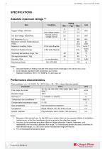
SPECIFICATIONS Absolute maximum ratings (1) Item Supply voltage, VDDmax I2C bus voltage, VDDIOmax Low voltage version Normal and low voltage version I2C frequency, fI2Cmax Maximum common mode pressure, Pmax Maximum overflow, Qmax of full scale flowrate Maximum flowrate change of full scale flowrate Operating temperature range, Top Storage temperature, Tstg Mechanical shock Notes: 1. Absolute Maximum Ratings indicate limits beyond which damage to the device may occur. 2. sccm denotes standard cubic centimeters per minute. Standard conditions: 20°C, 101.325kPa, dry and clean air Performance...
カタログの4ページ目を開く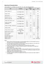
Electrical Characteristics (Test conditions: VDD = 8-15VDC, Ta = 20°C, RHa = 30…70%, unless otherwise stated) Item Supply current Minimum output load Analog output (rated), Vout (3) 1 Low voltage version Low voltage version Analog null voltage - bidirectional Analog null voltage unidirectional Digital and analog output analog & digital output I2C Normal and low voltage version Analog null drift Analog maximum output (5) Digital maximum output I2C bus voltage (6) Resolution digital output Digital null offset (8) Digital null drift Notes: 1. Warm-up time is the time from power on to the first...
カタログの5ページ目を開く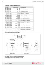
Pressure drop characteristics Part no. Flow Range Pressure drop MECHANICAL DIMENSIONS Flow direction Flow direction from left to right for uni-directional sensors. Please refer t
カタログの6ページ目を開く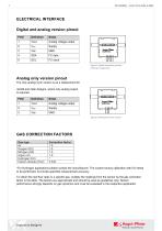
ELECTRICAL INTERFACE Digital and analog version pinout Pin# Analog voltage output I2C clock Figure 2 Digital and analog version (VI2C) pin assignment Analog only version pinout The only analog 3-pin version is as a replacement for retrofit and older designs, where only analog output is required. Pin# Analog voltage output GND Figure 3 Analog only 3-pin version GAS CORRECTION FACTORS Gas type Air Oxygen (O2) Nitrogen (N2) Argon (Ar) Hydrogen (H2) Carbon dioxide (CO2) *For Hydrogen applications please contact the manufacturer. The custom factory calibration with H2 needs to be performed, to...
カタログの7ページ目を開く
TYPICAL ANALOG OUTPUT
カタログの8ページ目を開く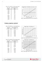
TYPICAL DIGITAL OUTPUT
カタログの9ページ目を開く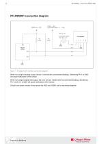
Figure 7. Analog and I2C interface connection diagram When not using the analog output, the pin 1 shall be left unconnected (floating). Shortening Pin 1 to GND will cause malfunction of the sensor. When not using the digital I2C output, the pin 4 and pin 5 shall be left unconnected (floating). Shortening Pin 4 and/ or 5 to GND will cause malfunction of the sensor. Only for low power version of the sensor the VDD and VDDIO can be connected together.
カタログの10ページ目を開く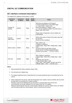
DIGITAL I2C COMMUNICATION I2C interface command description The default I2C address of the sensor is 0x50. Command Name Read/ Write Width (Byte) Notes Write the new address in 8-bit format It will be transformed to 7-bit (shifted right) i.e.: 0x0A (8-bit) -> 0x05 (7-bit) Send new address in 2 Bytes + CRC i.e.: new I2C address is 0x05 (7-bit), then send 3 Bytes: 0x00, 0x0A, 0x36 Please refer to Application note for details and code sample Flowrate offset reset Serial number Flow rate Write to the sensor 2-bytes of any fixed value (will be ignored). Ensure no-flow conditions HEX, ASCII code...
カタログの11ページ目を開く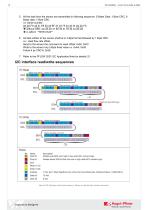
5. All the data from the sensor are transmitted in following sequence: 2-Bytes Data, 1 Byte CRC, 2Bytes data, 1-Byte CRC. i.e: Serial number: 2A 2A FA 42 31 E6 52 33 BF 31 33 75 34 33 34 2A 2A FA without CRC: 2A 2A 42 31 52 33 31 33 34 33 2A 2A in ASCII: **B1R31343** 6. All data written to the sensor shall be in 2-Byte format followed by 1 Byte CRC. i.e.: reset flow rate offset: Send to the sensor the command to reset offset: 0x00, 0xF0 Write to the sensor any 2-Byte fixed value i.e. 0xAA, 0x55 Follow it by CRC-8: 0x36 7. Refer to the PFLOW 2001 I2C Application Note for details [1] I2C...
カタログの12ページ目を開く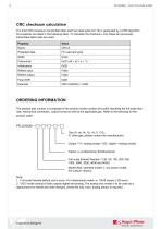
CRC checksum calculation The 8-bit CRC checksum transmitted after each two data bytes (int 16) is generated by a CRC algorithm. Its properties are listed in the following table. To calculate the checksum, only these two previously transmitted data bytes are used. Property Protected data Reflect input Reflect output ORDERING INFORMATION The product part number is composed of the product model number and suffix indicating the full-scale flow rate, mechanical connection, output format as well as the applicable gas. Refer to the following for the product order: PFLOW2001 Gas (A: air, N2, O2,...
カタログの13ページ目を開く
We are here for you. Addresses and Contacts. Headquarter Switzerland: Office Germany: Angst+Pfister Sensors and Power AG Angst+Pfister Sensors and Power Deutschland GmbH Scan here and get an overview of personal contacts! for sensors and power solutions
カタログの14ページ目を開くAngst+Pfister Sensors and Power AGのすべてのカタログと技術パンフレット
-
 SQ-UST_L_0105-01
4 ページ
-
 SQ-UST_L_0104-01
4 ページ
-
 SQ-UST_L_0103-01
4 ページ
-
 SQ-UST_L_0003-01
3 ページ
-
 SQ-UST_L_0002-01
3 ページ
-
 SQ-UST_L_0001-01
3 ページ
-
 PFLOW Series
5 ページ
-
 Model PFLOW3000 Series
16 ページ
-
 PZA-MC25-N/P
2 ページ
-
 PEWA100
9 ページ
-
 HLP-80H series
5 ページ
-
 HLP-40H series
5 ページ
-
 HBG-60P series
6 ページ
-
 UHP-750 series
6 ページ
-
 XLG-50 seri es
9 ページ
-
 DAP-04 series
8 ページ
-
 POB-30 series
11 ページ
-
 RHP-1U Rack System
9 ページ
-
 RFP-M8M4-5A
5 ページ
-
 RFP-M5M3-3A
4 ページ
-
 RFP-M2M3-3A
4 ページ
-
 RFP-M1M3-3A
4 ページ
-
 NCL CL1 01
4 ページ
-
 IRL RGB 01
4 ページ
-
 IRL CL2 01
4 ページ
-
 MSR385WD
3 ページ
-
 MSR145WD
3 ページ
-
 MSR 145
3 ページ
-
 M2029
M20293 ページ
-
 MSR165
3 ページ
-
 CRM102.1
33 ページ
-
 CRM200
39 ページ
-
 CRM100
37 ページ
-
 FPM
FPM4 ページ
-
 FGN
FGN4 ページ
-
 FPN
FPN4 ページ
-
 PBM220-A14N series
14 ページ
-
 PBM220 series
15 ページ
-
 PBM210-A20K Series
14 ページ
-
 STX Series – Model 13A
11 ページ
-
 CCD Series – Model 54D
20 ページ
-
 APB2Series
5 ページ
-
 AP4Series
5 ページ
-
 AP2Series
5 ページ
-
 PHPS-7500 OEM
6 ページ
-
 PPCP3-M1
10 ページ
-
 AG4Series
6 ページ
-
 AG2Series
5 ページ
-
 New Pewatron brochure
11 ページ
-
 GST220A
4 ページ
-
 GSM40B
6 ページ
-
 GSM36B
4 ページ
-
 GSC25E
5 ページ
-
 TDR-480
5 ページ
-
 GC120
GC1204 ページ
-
 HDR-30
5 ページ
-
 GSM220A
6 ページ
-
 EPP-400
5 ページ
-
 ENP-120
5 ページ
-
 ENC-120
6 ページ
-
 ATX-100
4 ページ
-
 RPS-200
7 ページ
-
 APBR30X75
2 ページ
-
 APBR30X60
2 ページ
-
 APBR 30X50 MM
2 ページ
-
 PSB54/16
2 ページ
-
 PSB54/14
2 ページ
-
 PSB36T/16
2 ページ
-
 PSB35T/12
2 ページ
-
 PSB25T/16
2 ページ
-
 PSB25T/12
2 ページ
-
 PSB21/12
2 ページ
-
 PSB 21
2 ページ
-
 AD-Series
16 ページ
-
 DMU11
DMU113 ページ
-
 HDR-30 series
5 ページ
-
 DMU30-01
25 ページ
-
 DMU30
DMU303 ページ
-
 DKA30 serie s
2 ページ
-
 DCW12
DCW122 ページ
-
 DCW05
DCW052 ページ
-
 EH - EF 80 C/P/K
3 ページ
-
 7S Series
3 ページ
-
 Model CE36M
3 ページ
-
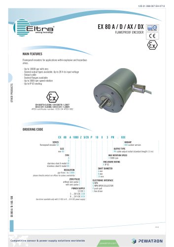 EX 80 A
3 ページ
-
 UFO
UFO3 ページ
-
 UFO-M2
3 ページ
-
 Dummy DC-Motoren
2 ページ
-
 GC30E
GC30E3 ページ
-
 RPS-400
11 ページ
-
 GC 330
4 ページ
-
 EL30
EL303 ページ
-
 EA PROFIBUS
7 ページ
-
 EAMW
EAMW3 ページ
-
 AAM58
AAM584 ページ
-
 EAM36
EAM363 ページ
-
 CARBONOXY25
2 ページ
-
 CARBONDIO-%
2 ページ
-
 FCX-ML25-EXTERN-CH
14 ページ
-
 FCX-MC25-CH
3 ページ
-
 FCX-MC05-CH
3 ページ
-
 FCX-TR0025
4 ページ
-
 LP-10HA
3 ページ
-
 FCX-UC-CH
9 ページ
-
 901.1-EX
5 ページ
-
 FC22
FC223 ページ
-
 MILLINEWTON
3 ページ
-
 PFLOW10U-2210
5 ページ
-
 901.1
901.15 ページ
-
 HX-EP
HX-EP6 ページ
-
 VQ548MP & MP-7217
5 ページ
-
 Air quality sensing
6 ページ
-
 Tailor-made
10 ページ
-
 RAZTEC
13 ページ
-
 The SGX-SureCO
3 ページ
-
 930 Climair
5 ページ
-
 MSP-600 600W AC/DC
5 ページ
-
 Pewatron_Flyer_EN
8 ページ


