
カタログの抜粋
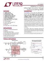
LTC5551 300MHz to 3.5GHz Ultra-High Dynamic Range Downconverting Mixer Description Features +36dBm Input IP3 n 2.4dB Conversion Gain n Low Noise Figure: <10dB n +18dBm Ultra High Input P1dB n 670mW Power Consumption n 2.5V to 3.6V Operation n 50Ω Single-Ended RF and LO Inputs n 0dBm LO Drive Level n Low Power Mode n –40°C to 105°C Operation (T ) C n Small Solution Size n Enable Pin n 16-Lead (4mm × 4mm) QFN Package The LTC®5551 is a 2.5V to 3.6V mixer optimized for RF downconverting mixer applications that require very high dynamic range. The LTC5551 covers the 300MHz to 3.5GHz RF Frequency range with LO frequency range of 200MHz to 3.5GHz. The LTC5551 provides very high IIP3 and P1dB with low power consumption. A typical application is a basestation receiver covering 700MHz to 2.7GHz frequency range. The RF input can be matched for a wide range of frequencies and the IF is usable up to 1GHz. A low power mode is activated by pulling the ISEL pin high, reducing the power consumption by about 1/3, however, with a corresponding reduction in IIP3 to approximately +29dBm. The mixer can also be turned on or off by using the EN pin. The LTC5551’s high level of integration minimizes the total solution cost, board space and system level variation, while providing the highest dynamic range for demanding receiver applications. GSM, LTE, LTE-Advanced Basestations Repeaters DPD Observation Receiver Public Safety Radios, Military and Defense Avionics Radios and TCAS Transponders Active Phased-Array Antennas White-Space Radio Receiver L, LT, LTC, LTM, Linear Technology and the Linear logo are registered trademarks of Linear Technology Corporation. All other trademarks are the property of their respective owners. Typical Application Wideband Receiver 1nF VCC 3.3V Mixer Conversion Gain and IIP3 vs IF Frequency (Low-Side LO) 2 NORMAL POWER MODE LOW POWER MODE
カタログの1ページ目を開く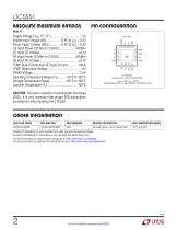
LTC5551 Absolute Maximum Ratings UF PACKAGE 16-LEAD (4mm × 4mm) PLASTIC QFN TJMAX = 150°C, θJC = 6°C/W EXPOSED PAD (PIN 17) IS GND, MUST BE SOLDERED TO PCB CAUTION: This part is sensitive to electrostatic discharge (ESD). It is very important that proper ESD precautions be observed when handling the LTC5551. Order Information LEAD FREE FINISH PART MARKING PACKAGE DESCRIPTION CASE TEMPERATURE RANGE Consult LTC Marketing for parts specified with wider operating temperature ranges. Consult LTC Marketing for information on non-standard lead based finish parts. For more information on lead free...
カタログの2ページ目を開く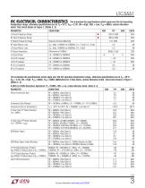
The l denotes the specifications which apply over the full operating temperature range, otherwise specifications are at TC = 25°C. VCC = 3.3V, EN = High, ISEL = Low, PLO = 0dBm, unless otherwise noted. Test circuit shown in Figure 1. (Notes 2, 3) PARAMETER LO Input Frequency Range RF Input Frequency Range IF Output Frequency Range Requires External Matching RF Input Return Loss LO Input Return Loss The l denotes the specifications which apply over the full operating temperature range, otherwise specifications are at TC = 25°C. VCC = 3.3V, EN = High, PLO = 0dBm, PRF = 0dBm (0dBm/tone for...
カタログの3ページ目を開く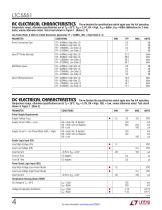
The l denotes the specifications which apply over the full operating temperature range, otherwise specifications are at TA = 25°C. VCC = 3.3V, EN = High, PLO = 0dBm, PRF = 0dBm (0dBm/tone for 2-tone tests), unless otherwise noted. Test circuit shown in Figure 1. (Notes 2, 3) Low Power Mode, 0.3GHz to 3.5GHz Downmixer Application: IF = 153MHz, ISEL = High (Notes 2, 3) PARAMETER Power Conversion Gain RF = 400MHz, High Side LO RF = 850MHz, High Side LO RF = 1950MHz, Low Side LO RF = 2700MHz, Low Side LO Input 3rd Order Intercept RF = 400MHz, High Side LO RF = 850MHz, High Side LO RF = 1950MHz,...
カタログの4ページ目を開く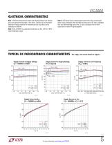
LTC5551 Electrical Characteristics Note 1: Stresses beyond those listed under Absolute Maximum Ratings may cause permanent damage to the device. Exposure to any Absolute Maximum Rating condition for extended periods may affect device reliability and lifetime. Note 2: The LTC5551 is guaranteed functional over the –40°C to 105°C case temperature range. Note 3: SSB Noise Figure measurements performed with a small-signal noise source, bandpass filter and 6dB matching pad on RF input, bandpass filter and 6dB matching pad on the LO input, bandpass filter on the IF output and no other RF signals...
カタログの5ページ目を開く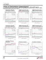
LTC5551 Typical AC Performance Characteristics 1100MHz to 2700MHz application. VCC = 3.3V, EN = High, ISEL = Low, TC = 25°C, PLO = 0dBm, PRF = 0dBm (0dBm/tone for two-tone IIP3 tests, ∆f = 2MHz), IF = 153MHz, unless otherwise noted. Test circuit shown in Figure 1. Input P1dB vs RF Frequency (Low Side LO) 2550MHz Conversion Gain, IIP3 and NF vs LO Power (High Side LO) 1950MHz Conversion Gain, IIP3 and NF vs LO Power (High Side LO) Conversion Gain, IIP3 and NF vs RF Frequency (High Side LO) 33 2550MHz Conversion Gain, IIP3 and NF vs LO Power (Low Side LO) 1950MHz Conversion Gain, IIP3 and NF...
カタログの6ページ目を開く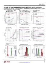
LTC5551 Typical AC Performance Characteristics 1100MHz to 2700MHz application. VCC = 3.3V, EN = High, ISEL = Low, TC = 25°C, PLO = 0dBm, PRF = 0dBm (0dBm/tone for two-tone IIP3 tests, ∆f = 2MHz), IF = 153MHz, unless otherwise noted. Test circuit shown in Figure 1. Single-Tone IF Output Power, 2 × 2 and 3 × 3 Spurs vs RF Input Power 20 RF = 1950MHz LOW SIDE LO HIGH SIDE LO 4 RF = 1950MHz LOW SIDE LO HIGH SIDE LO 3 1950MHz Conversion Gain Histogram 60 Conversion Gain, IIP3, P1dB and SSB NF vs Supply Voltage Conversion Gain, IIP3 and SSB NF vs Temperature SSB Noise Figure vs RF Blocker Level...
カタログの7ページ目を開く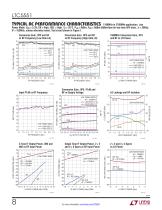
LTC5551 Typical AC Performance Characteristics 1100MHz to 2700MHz application. Low Power Mode. VCC = 3.3V, EN = High, ISEL = High, TC = 25°C, PLO = 0dBm, PRF = 0dBm (0dBm/tone for two-tone IIP3 tests, ∆f = 2MHz), IF = 153MHz, unless otherwise noted. Test circuit shown in Figure 1. Conversion Gain, IIP3 and NF vs RF Frequency (Low Side LO) Conversion Gain, IIP3 and NF vs RF Frequency (High Side LO) 31 28 14 13 LOW POWER MODE LOW SIDE LO HIGH SIDE LO 1.3 Single Tone IF Output Power, 2 × 2 and 3 × 3 Spurs vs RF Input Power LOW POWER MODE RF = 1950MHz LOW SIDE LO 4 HIGH SIDE LO 2-Tone IF Output...
カタログの8ページ目を開くADI/リニアテクノロジーのすべてのカタログと技術パンフレット
-
 LTC2068
30 ページ
-
 LTC6373
34 ページ
-
 ADL9006
16 ページ
-
 ADL8104
23 ページ
-
 AD4115
52 ページ
-
 ADUM7702
22 ページ
-
 AD7383
33 ページ
-
 AD7384
33 ページ
-
 AD4114
49 ページ
-
 ADUM7704
22 ページ
-
 AD7134
86 ページ
-
 LTspice IV
53 ページ
-
 New Products Catalog
43 ページ
-
 RF/IF Amplifiers
9 ページ
-
 SAR ADC Drivers
2 ページ
-
 SmartMesh Brochure
8 ページ
-
 INDUSTRIAL SIGNAL CHAIN
24 ページ
-
 Wireless & RF Solution
36 ページ
-
 LT6656 - 1
18 ページ


カタログアーカイブ
-
 New Products Catalog
39 ページ


